Inst ToolsInst ToolsInst Tools
  • Courses
  • Automation
    • PLC
    • Control System
    • Safety System
    • Communication
    • Fire & Gas System
  • Instrumentation
    • Design
    • Pressure
    • Temperature
    • Flow
    • Level
    • Vibration
    • Analyzer
    • Control Valve
    • Switch
    • Calibration
    • Erection & Commissioning
  • Interview
    • Instrumentation
    • Electrical
    • Electronics
    • Practical
  • Q&A
    • Instrumentation
    • Control System
    • Electrical
    • Electronics
    • Analog Electronics
    • Digital Electronics
    • Power Electronics
    • Microprocessor
  • Request
Search
  • Books
  • Software
  • Projects
  • Process
  • Tools
  • Basics
  • Formula
  • Power Plant
  • Root Cause Analysis
  • Electrical Basics
  • Animation
  • Standards
  • 4-20 mA Course
  • Siemens PLC Course
Reading: Elevator PLC Ladder Logic
Share
Font ResizerAa
Inst ToolsInst Tools
Font ResizerAa
  • Courses
  • Design
  • PLC
  • Interview
  • Control System
Search
  • Courses
  • Automation
    • PLC
    • Control System
    • Safety System
    • Communication
    • Fire & Gas System
  • Instrumentation
    • Design
    • Pressure
    • Temperature
    • Flow
    • Level
    • Vibration
    • Analyzer
    • Control Valve
    • Switch
    • Calibration
    • Erection & Commissioning
  • Interview
    • Instrumentation
    • Electrical
    • Electronics
    • Practical
  • Q&A
    • Instrumentation
    • Control System
    • Electrical
    • Electronics
    • Analog Electronics
    • Digital Electronics
    • Power Electronics
    • Microprocessor
  • Request
Follow US
All rights reserved. Reproduction in whole or in part without written permission is prohibited.
Inst Tools > Blog > PLC Tutorials > Elevator PLC Ladder Logic

Elevator PLC Ladder Logic

Last updated: March 4, 2021 3:49 pm
Editorial Staff
PLC Tutorials
6 Comments
Share
5 Min Read
SHARE

Design a PLC program to execute the elevator system in a 2-floor apartment using Allen Bradley PLC programming.
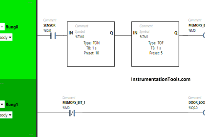
Contents
Elevator PLC LogicElevator Logic Inputs and OutputsElevator PLC LogicElevator Logic DescriptionRUNG 0000RUNG 0001RUNG 0002Rung 0003Rung 0004, 0005, 0006Rung 0007, 0008, 0009RUNG 0010, 0011RUNG 0012, 0013RUNG 0014, 0015RUNG 0016RUNG 0017RUNG 0018RUNG 0019Conclusion:

Elevator PLC Logic

Elevator PLC Ladder Logic

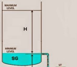
In the above picture, there are totally two floors.

There are two user panels. One is inside the lift and other is outside the lift.

Limit switches are used to locate and stop the lift at each floor.

Priority is given to the first input.

Elevator Logic Inputs and Outputs

Elevator Logic Inputs and Outputs

Elevator PLC Logic

Elevator PLC Logic
Elevator PLC Programming
3 floor elevator logic
PLC Program for Elevator
PLC based Elevator Control System
PLC Logic for Lift

Elevator Logic Description

RUNG 0000

Latching rung to operate the system through Master Start and Stop PB.

RUNG 0001

Starting the Operation using start latch, Ground floor PB is pushed to turn on latch coil to store the output of status when the ground limit switch is off.

RUNG 0002

First floor PB is pushed to turn on the latch coil to store the output of status when the First limit switch is off.

Rung 0003

Second floor  PB is pushed to turn on the latch coil to store the output of status when the Second limit switch is off.

Rung 0004, 0005, 0006

In some cases,if someone pressed ground floor PB/First floor PB, the program will check where the lift is if it is in the second floor or the first floor, Down Motor will turn ON to get the lift to the respective floor.

For interlocking, normally closed switch of ground limit switch and first-floor switch is used in Rung 0006

Rung 0007, 0008, 0009

In some cases, if someone pressed the second floor PB/First-floor Pushbuttons (PB), the program will check where the lift is, if it is in the ground floor or the first floor, UP Motor will turn ON to get the lift to the respective floor.

For interlocking, normally closed switch of second-floor limit switch and first-floor switch is used in Rung 0009

RUNG 0010, 0011

To open the lift door when it reaching floor  Binary bits are used to store the status of ground floor PB and ground Limit switch.

RUNG 0012, 0013

To open the lift door when it reaching the floor , Binary bits are used to store the status of First floor PB and First Limit switch.

RUNG 0014, 0015

To open the lift door when it reaching the floor , Binary bits are used to store the status of Third floor PB and third-floor Limit switch.

RUNG 0016

From the previous rungs memories, an Open door motor is turned ON with three interlocking like closed-door motor, Timer enables, UP/DOWN motor.

RUNG 0017

When the open door limit switch is turned to on, the Open motor door should stop and timer needs to turn on to give time delay of 5s to close door motor.

RUNG 0018

When timer done turned on, close door motor should ON until closed limit switch is turned ON.

RUNG 0019

If no PB is turned on after getting into lift takes 10secs delay to open lift door again. If any PB is pressed, it will perform the respective operations.

The program runs continuously until STOP PB is pressed

Note: We can reduce the number of memories used.

Conclusion:

The above-explained elevator control using PLC is for example only. It may vary from real-time. There are many concepts to program elevator, this program is one of the types.

Author : Hema Sundaresan

If you liked this article, then please subscribe to our YouTube Channel for PLC and SCADA video tutorials.

You can also follow us on Facebook and Twitter to receive daily updates.

Read Next:

PLC Program for Motor Starter

Academic PLC Projects List

SCADA Objective Questions

GE PLC Programming

PLC and MCC control video

Don't Miss Our Updates
Be the first to get exclusive content straight to your email.
We promise not to spam you. You can unsubscribe at any time.
Invalid email address
You've successfully subscribed !

Continue Reading

Industrial Automation Pre-Engineering Design Documents – Project & Process
How to Interchange ON Delay Timer and OFF Delay Timer in a PLC
Control Two Motors in Sequence after Time Delay – Circuit, Operation
Automatic Paper Cutting Machine Using CX-Programmer
Workstation Healthiness Checks
PLC Program for Continuous Filling Operation
Share This Article
Facebook Whatsapp Whatsapp LinkedIn Copy Link
Share
6 Comments
  • Berihu welday says:
    July 20, 2019 at 11:08 am

    Your Comment very good explanation

    Reply
    • MOSELINE DE OLIVEIRA COELHO says:
      October 7, 2021 at 8:35 am

      What plc software is used?

      Reply
  • rutger says:
    July 5, 2021 at 3:01 pm

    Hello,

    iam trying to convert this plc program to GX developer.
    what can i use for the Latch comando??
    Gx developer does not use this.
    I am making a lift in my house for my disabled wife.
    i have all the hardware installed, and i can use some help with programming the plc.

    many thanks for this example,
    Rutger ten Wolthuis

    Reply
  • roberto says:
    October 1, 2021 at 1:21 pm

    Memories B3:0 / 12, B3:0 / 13, and B3:0 / 14 once activated will stay on until the program is stopped. Is that correct ? Aren’t you missing a stop condition for them ?

    Reply
  • Elzabid says:
    May 27, 2025 at 7:55 am

    I tried this program and it is very helpful but I found an error. Did you forget to use the interlock and safety system on it?

    Reply
  • Peter Zetterberg says:
    May 27, 2025 at 7:24 pm

    It dosent prioritises correct. if button level 4 is active and then button level 1 and then button level 4 the peopel on floor 2 and 3 never gets the elevator

    Reply

Leave a Reply Cancel reply

Your email address will not be published. Required fields are marked *

Stay Connected

128.3kFollowersLike
69.1kFollowersFollow
210kSubscribersSubscribe
38kFollowersFollow

Categories

Explore More

Scale and Normalize Instructions in PLC
Automatic Railway Crossing Gate Control PLC Program
SAVE and BR Memory Instructions in Siemens PLC Programming
Connecting Blocks in Functional Block Diagram – Studio 5000
PLC Programming Example using Limit Switch
Difference Between PLC and CNC Machine
Job Skills Required for Industrial Electrical Maintenance
Mitsubishi Electric GOC Controllers

Keep Learning

How to Select the Right Encoder for Your Machine

How to Select the Right Encoder for Your Machine?

PLC Program for Password Management using Structured Text

PLC Program for Password Management using Structured Text

PLC Commissioning and Testing

PLC Commissioning and Testing Procedure (Programmable Logic Controller)

DRUM DB

Siemens Drum block for Sequencer Operation

Switch NO or NC Contact

Normally-open and Normally-closed Switch Contacts

A Typical Sequential Function Chart

What is Sequential Function Chart (SFC?)

PLC Programming Sequence Logic

PLC Programming to Control Lights in a Sequence

Omron PLC Example

Design a Water Pump PLC Program using CX-Programmer

Learn More

Top 100 LabVIEW Projects for Engineering Students

Top 100 LabVIEW Projects for Engineering Students

The Hardware Structure of DCS

DCS Applications and Hardware Structure of Plant Automation

Thermocouple Standard

Thermocouple Details

limit-switch-works

How Limit Switch Works ?

Applications of CNC Machining

Important Applications of Rapid Prototype CNC Machining Services

Smart Transmitter Calibration Tutorial

Smart Transmitter Calibration Tutorial Part 1

dissolved-oxygen-probe-calibration-procedure

Dissolved oxygen probe calibration procedure

Control Valve pressure recovery

What is Control Valve Flashing ?

Menu

  • About
  • Privacy Policy
  • Copyright

Quick Links

  • Learn PLC
  • Helping Hand
  • Part Time Job

YouTube Subscribe

Follow US
All rights reserved. Reproduction in whole or in part without written permission is prohibited.
Welcome Back!

Sign in to your account

Username or Email Address
Password

Lost your password?