This is an elevator control application using a PLC Program with 5-second floor stops before moving to the next floor.
Please note that this program only shows a certain part of the logic related to the elevator programming. This is for educational purposes only.
Elevator Control
Problem Statement:
Design a PLC ladder logic for the following application.
We are using one toggle switch to control the Elevator.
The elevator should stop at each floor for 5 seconds before moving to the next floor.
Online PLC Training
Inst Tools provides you with the best online PLC training tutorials and courses. You can access these on our YouTube channel.
Inputs and Outputs
Digital Inputs:
Start Button: I0.0
Digital Outputs:
Elevator: Q0.0
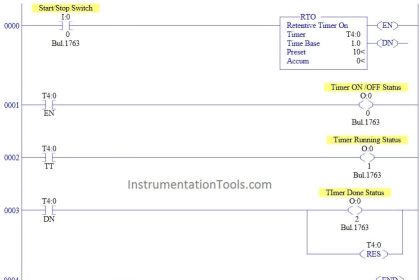
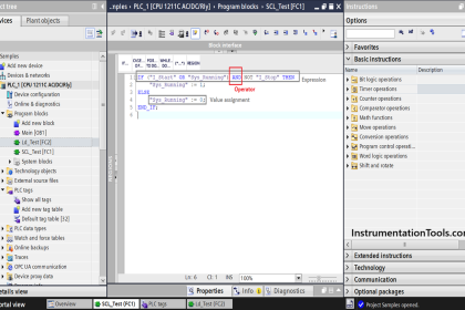
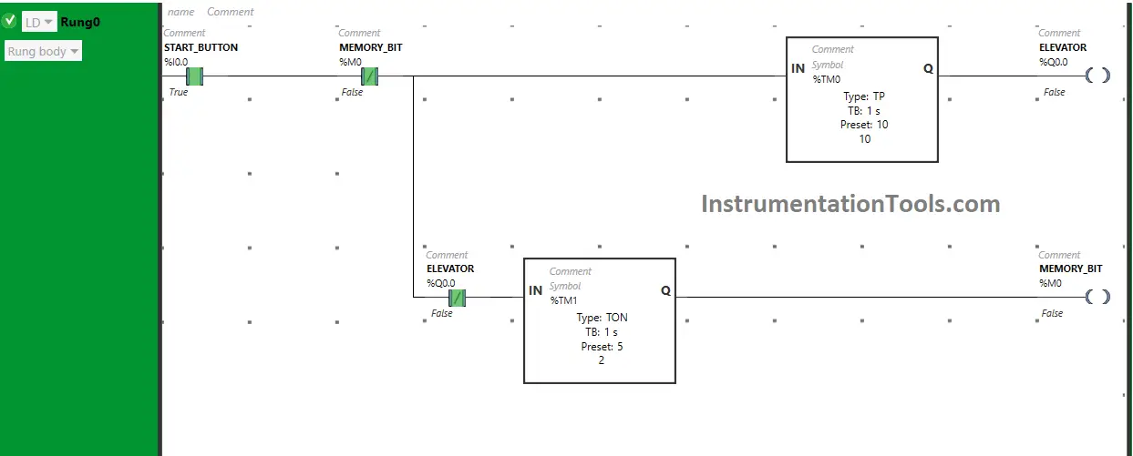
Ladder Logic
Program Description
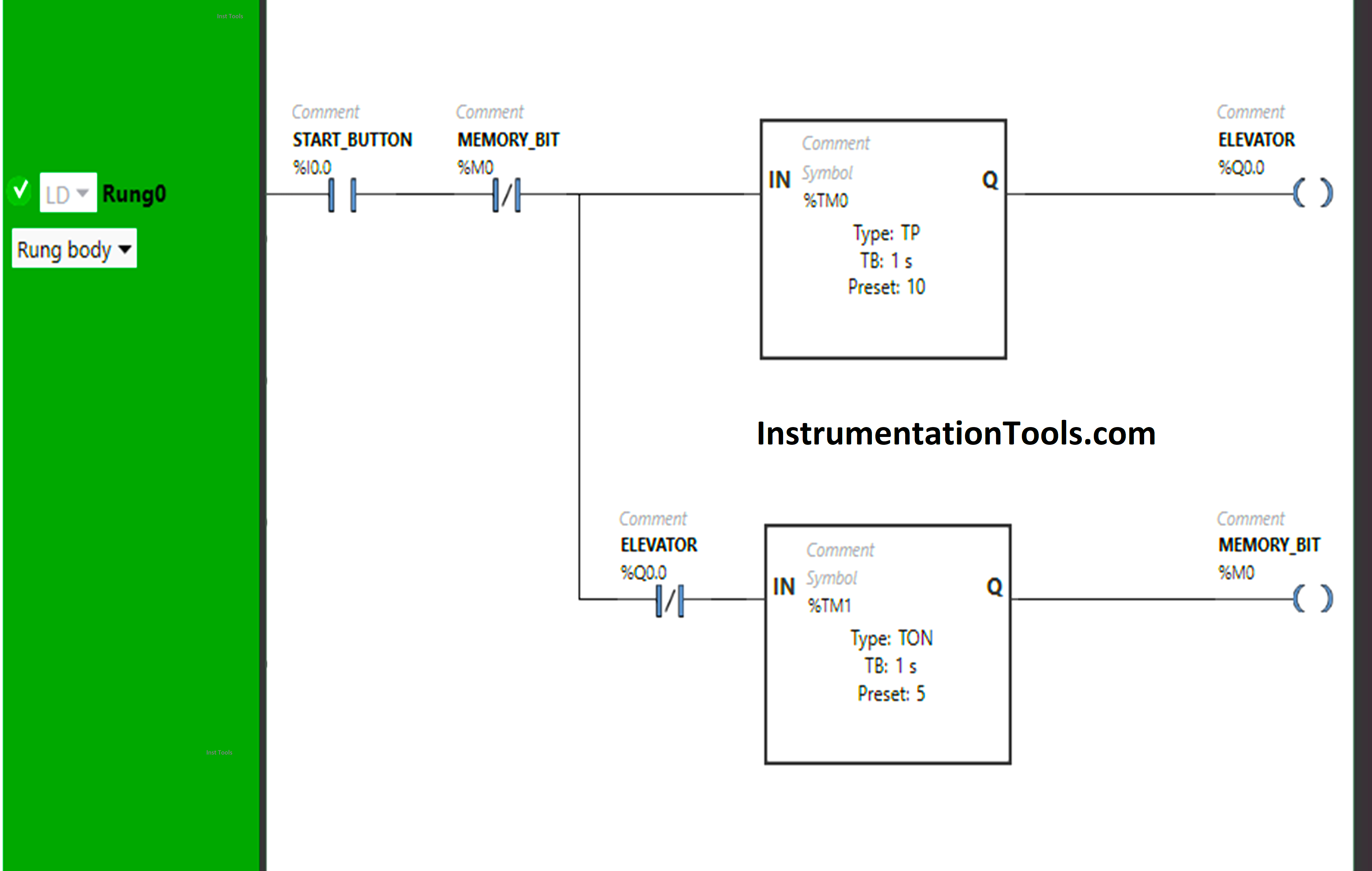
We have used Normally Open Contact for the Start Button (I0.0).
Normally Open Contact is used for the Start Button (I0.0) to Turn ON the output Elevator (Q0.0).
Timer-type TP is used to Turn ON the output Elevator (Q0.0) for a limited time.
Normally Closed Contact is used for Memory Bit (M0) to restart the output Elevator (Q0.0).
Normally Closed Contact is used for the Elevator (Q0.0) to turn ON the Memory Bit (M0).
Timer Function Block type TON is used to delay the turning ON time of Memory Bit (M0).
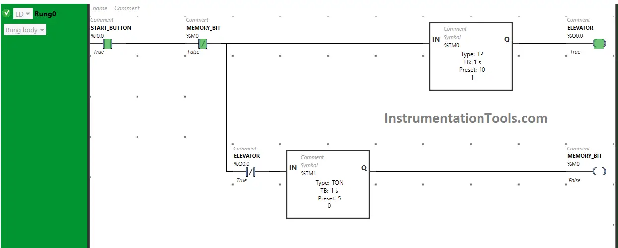
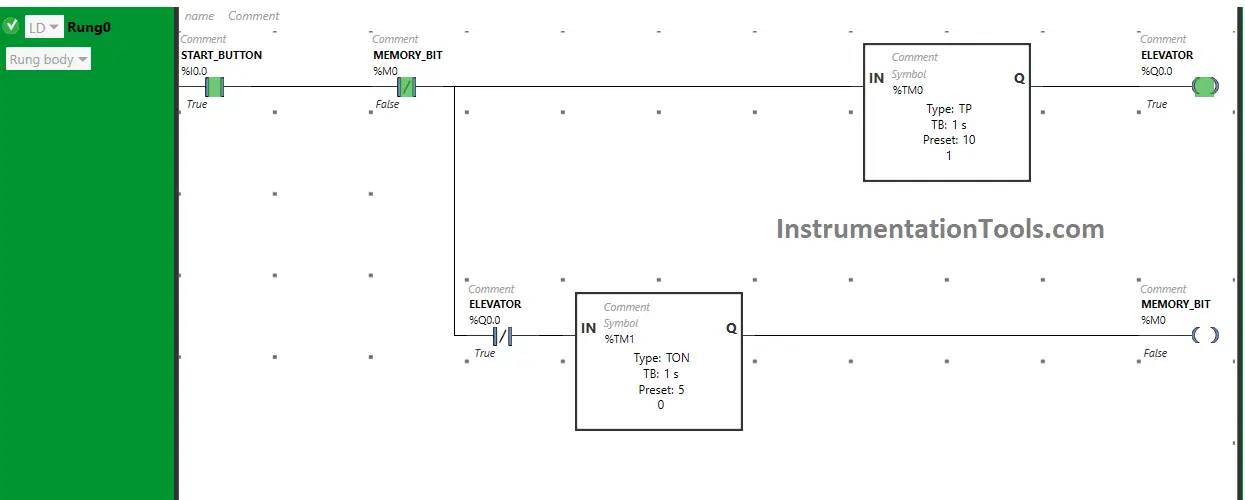
PLC Logic Simulation
Let’s simulate the PLC program.
When the Start Button(I0.0) is turned ON, the output Elevator (Q0.0) turns ON or the Elevator starts moving but for a limited time because Timer Function Block type TP is used to turn ON the output Elevator (Q0.0) for a limited time. The time is set to 10 seconds.
After 10 seconds, the output elevator (Q0.0) turns OFF or the Elevator stops moving after reaching the next floor but only for 5 seconds because When the output Elevator (Q0.0) turns OFF, Normally Closed Contact used for the Elevator that is used to turn ON Memory Bit (M0) will be in the false state and Memory Bit (M0) will turn ON after 5 seconds as Timer Function Block type TON is used to delay the turning ON time of the Memory Bit (M0).
After 5 seconds, the Memory Bit will turn ON but it will turn OFF immediately as Normally Closed Contact used for the Memory Bit (M0) to restart the output Elevator (Q0.0).
So, When the Start Button (I0.0) is turned ON, the output elevator (Q0.0) starts moving. After 10 seconds, the output Elevator (Q0.0) stops as the Timer Function Block is used and the timer is set to 10 seconds.
When the output Elevator (Q0.0) Stops, Normally Closed Contact used for the Elevator will be in a false state and pass the signal to turn ON the Memory Bit (M0) after 5 seconds as the Timer Function Block type TON is used and the timer is set to 5 seconds.
Memory Bit (M0) will turn OFF immediately because Normally Closed Contact is used for Memory Bit (M0) that is used to restart the output Elevator (Q0.0).
So, When Memory Bit (M0) turns OFF immediately, Normally Close Contact used for Memory Bit (M0) will be in the false state and pass the signal to restart the output Elevator (Q0.0).
If you liked this article, please subscribe to our YouTube Channel for PLC and SCADA video tutorials.
You can also follow us on Facebook and Twitter to receive daily updates.
Read Next:
- PLC Programming to Control a Pump
- Manufacturing Line Assembly PLC Logic
- PLC Ladder Logic Classroom Bell System
- Batch Mixing PLC Ladder Logic Program
- PLC Pushbutton and Motor Ladder Logic