Electrical trace heating, or as it is often called heat tracing, refers to the process of maintaining or raising the temperature of instrument impulse lines, pipes, and even vessels through specially designed cables.
In simple terms, the application of a compensating heat source.
Electrical Heat Tracing
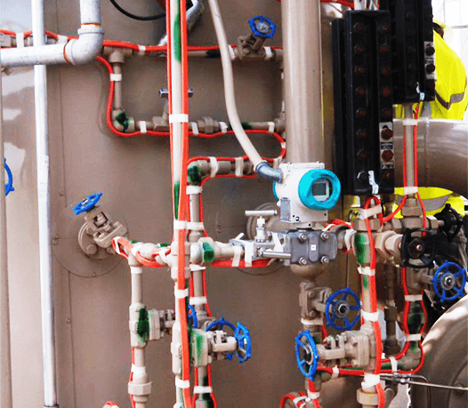
Image Credits: TSI Services
Electrical heating is widely used. When heating elements are selected, care should be exercised to ensure that they are not potential sources of ignition. Several types of cable are available (for example, mineral insulated and self-limiting).
Fittings, relays, and thermostats must be suitable for the area classification. Guidance in meeting these requirements is given in NFPA 70, Article 500. Local codes must also be followed.
Heat tracing is usually considered in the following circumstances:
- When there is a risk of pipes freezing. In cold weather this is especially prevalent in dead legs or when there is little or no flow of a fluid susceptible to freezing in a line. Pipes and impulse lines that freeze can rupture therefore trace heating can prevent this.
- To maintain the temperature of a liquid system. Trace heating is often used in hot water systems.
- To maintain process temperatures for the smooth and efficient running of process plant and equipment. For example, heavy, or waxy oils flow better at higher temperatures therefore trace heating is often used on these lines.
Several considerations are involved in the design and installation of electrical heating to ensure that the heating system will operate properly during start-up and continued plant operation. The thermostat sensor must be located properly and set at the correct temperature. The thermostat should be installed so that its setting can be checked with the thermostat in place. A means of indicating that the cable is functioning properly is required.
Every pipe, vessel, and impulse line is subject to heat loss when its temperature is greater than ambient temperature. The rate of heat loss can be slowed by the use of thermal insulation, but this does not eliminate it. Electrical trace heating replaces some, or all, of the heat lost from the surface. The amount of heat replaced depends on what is to be achieved, i.e. freeze prevention, or temperature maintenance.
Control of the heat supplied can be from a simple on-off thermostat, e.g. the thermostat energizing the heat tracing when the temperature falls below the setpoint and de-energizes when the temperature is a couple of degrees above the setpoint or increasingly common control is supplied from microprocessor-based control and monitoring systems – either stand-alone or within the plant control system.
There are three types of heat tracing cables available:
- constant power cables,
- constant wattage cables, and
- self-regulating cables.
Each type of trace heating cable works differently, and the choice of cable is influenced by the intended application.
Constant Power Cable Tracing
Constant power heat tracing cable sometimes referred to as series resistance cable is made up of a high-resistance wire that is typically insulated and encased in a protective cover. When powered at its operating voltage, thermal energy is produced from the resistance of the wire.
Advantages of constant power trace heating cables include:
The advantage of a constant power heating cable is that it is generally inexpensive and is able to maintain very high temperatures (especially mineral insulated cables) for longer lines.
Mineral insulated cables are also good for maintaining lower temperatures on lines which can get extremely hot such as high-temperature steam lines.
Disadvantages of constant power trace heating cables include:
They are supplied in specific lengths and cannot be shortened in the field,
A break or failure anywhere along the length of a constant power cable will cause the entire cable to fail,
Care needs to be taken during installation that the cable is not crossed over itself as this can lead to the cable overheating and eventual burnout.
Constant Wattage Cable Tracing
A constant wattage cable is composed of multiple constant electric power zones, made by wrapping a fine heating element around two insulated parallel bus wires.
A notch is created in the insulation on the opposing sides of the conductors and a small heating circuit is then produced by fusing the heating element to the exposed conductor wire and this is repeated throughout the entire cable producing the power zones. There is then an inner jacket which separates the bus wires from the grounding braid.
Advantages of constant wattage trace heating cables include:
The major advantage of constant wattage trace heating cable is that this cable can be cut to length in the field due to its parallel circuitry. Another advantage is that constant wattage heating tapes can be joined using either a jointing kit or a trace heating junction box.
Disadvantages of constant wattage trace heating cables include:
As with constant power cables, constant wattage cables should not be crossed over itself as this can lead to them overheating and eventual burnout.
Constant wattage cable is always installed with a thermostat to control the power output of the cable, making it a very reliable heating source.
Self Regulating Cable Tracing
The self-regulating heating cable is most often called a tape rather than a cable i.e. self-regulating tape, or even self-limiting tape. Self-regulating tape adjusts heat output depending on the heat loss from the pipe work by varying its conductivity. As pipe temperature falls the electrical conductivity of the semi-conductive polymer core increases causing the tape to increase output. As the pipe temperature increases the conductivity reduces and output decreases.
The self-regulating tape uses two parallel bus wires which carry electricity but do not create significant heat. They are encased in a semi-conductive polymer. This polymer is loaded with carbon; as the polymer element heats, it allows less current to flow. The cables are manufactured and then irradiated and by varying both the carbon content and the dosage then different tape with different output characteristics can be produced.
Advantages of self-regulating trace heat tape include:
It can be cut to length in the field,
It is more energy-efficient as it is able to reduce its output at higher temperatures
It cannot overheat itself so will not burn out if inadvertently crossed over itself during installation. This makes them attractive for use in potentially hazardous areas.
Self-regulating tape does have some disadvantages, including:
It is not as reliable as series or constant wattage cables,
It has a specific maximum exposure temperature and if subjected to temperatures above this then the tape can be damaged beyond repair.
It is subject to high inrush currents on starting up so a higher rated contactor is required compared to other trace heating cables.
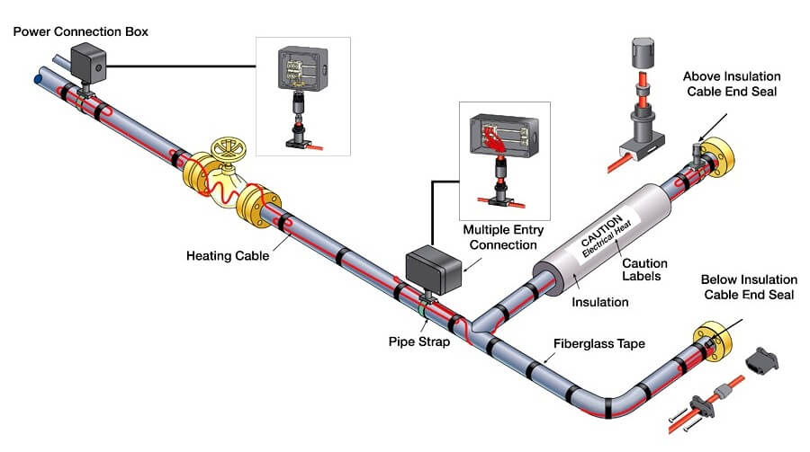
Image Credits: Process Heating
Interest to add any further points? Share with us through below comments section.
Author: Kalpit Patel
Read Next:
- Electrical Ground Loops
- Purging of Instruments
- Purged Impulse Lines
- Impulse Steam Traps
- Impulse Piping Installation


hi dear friends
thanks a lot for sharing this article about “heat tracing” with us
have a good day