Inst ToolsInst ToolsInst Tools
  • Courses
  • Automation
    • PLC
    • Control System
    • Safety System
    • Communication
    • Fire & Gas System
  • Instrumentation
    • Design
    • Pressure
    • Temperature
    • Flow
    • Level
    • Vibration
    • Analyzer
    • Control Valve
    • Switch
    • Calibration
    • Erection & Commissioning
  • Interview
    • Instrumentation
    • Electrical
    • Electronics
    • Practical
  • Q&A
    • Instrumentation
    • Control System
    • Electrical
    • Electronics
    • Analog Electronics
    • Digital Electronics
    • Power Electronics
    • Microprocessor
  • Request
Search
  • Books
  • Software
  • Projects
  • Process
  • Tools
  • Basics
  • Formula
  • Power Plant
  • Root Cause Analysis
  • Electrical Basics
  • Animation
  • Standards
  • 4-20 mA Course
  • Siemens PLC Course
Reading: Controller Components – Part 2 Objective Questions
Share
Notification Show More
Font ResizerAa
Inst ToolsInst Tools
Font ResizerAa
  • Courses
  • Design
  • PLC
  • Interview
  • Control System
Search
  • Courses
  • Automation
    • PLC
    • Control System
    • Safety System
    • Communication
    • Fire & Gas System
  • Instrumentation
    • Design
    • Pressure
    • Temperature
    • Flow
    • Level
    • Vibration
    • Analyzer
    • Control Valve
    • Switch
    • Calibration
    • Erection & Commissioning
  • Interview
    • Instrumentation
    • Electrical
    • Electronics
    • Practical
  • Q&A
    • Instrumentation
    • Control System
    • Electrical
    • Electronics
    • Analog Electronics
    • Digital Electronics
    • Power Electronics
    • Microprocessor
  • Request
Follow US
All rights reserved. Reproduction in whole or in part without written permission is prohibited.
Inst Tools > Blog > Multiple Choice Questions > Controller Components – Part 2 Objective Questions

Controller Components – Part 2 Objective Questions

Last updated: November 27, 2021 5:41 pm
Editorial Staff
Multiple Choice Questions
No Comments
Share
6 Min Read
SHARE

Controller Components – Part 2 Objective Questions

1. Different type of construction in permanent type DC magnet are :

a) Slotted armature type
b) Surface wound armature type
c) Surface wound rotating armature, stationary wound type.
d) All of the mentioned

Answer: d

Explanation: Permanent magnet are the hard magnets that have broad B-H curve and can not be used as the core of the transformer due to their high retentivity and can be constructed by various ways as described above.

2. Assertion (A): Slotted armature type in this armature is placed in slotted armature with DC windings placed inside the slots.
Reason (R): The construction is highly reliable and rugged but has high torque.

a) Both A and R are true and R is correct explanation of A
b) Both A and R are true but R is not correct explanation of A
c) A is true but R is false
d) A is false but R is true

Answer: b

Explanation: Slotted armature as the name indicates in which armature is paced in slots but high inertia is present causing higher torque and less used.

3. A much lower inertia in Surface wound armature type is obtained by placing the winding on a non-magnetic cylinder which rotates in annular space between permanent magnet stator and stationary rotor.

a) True
b) False

Answer: a

Explanation: Because of larger air gap strong permanent magnets are needed and much lower inertia is obtained by placing non-magnetic cylinder which rotates in annular space between permanent magnet stator and stationary rotor.

4. Lower inertia is obtained due to much larger gap and hence stronger magnets are used for this purpose.

a) True
b) False

Answer: a

Explanation: Stronger permanent magnets are used so as to cause lower inertia as in Surface wound rotating armature and stationary wound type.

5. PMDC when coupled to a rotating shaft would generate a voltage proportional to speed and thus would serve as____________

a) Tachometer
b) Servomotor
c) D.C. motor
d) A.C. motor

Answer: a

Explanation: Tachometer is a device that has relationship between voltage and speed and this is used in the controller to enhance the gain of the control system.

6. PMDC device is commonly employed for:

a) Speed feedback in speed control system
b) Internal velocity feedback loop of a position control system
c) This device is used in both speed feedback and internal velocity feedback control
d) None of the mentioned

Answer: c

Explanation: The current rating of this type of device is very small and it is to be connected to the input end of the OP-AMP.

7. Commutation process of a DC motor can be accomplished by solid devices (transistors and SCR’s).

a) True
b) False

Answer: a

Explanation: Commutation process refers to the process in the alternating current is used as input in the DC motor and in case of a DC motor this can be accomplished by solid devices as the IC’s and transistors.

8. DC motors are constructed using Permanent Magnet resulting in:

a) Higher torque/inertia ratio
b) Higher operating frequency
c) No filed losses
d) All of the mentioned

Answer: d

Explanation: DC motors are extensively using Permanent Magnets for its construction as they provide higher torque/inertia ratio, higher operating frequency, no field losses.

9. Speed of a permanent magnet DC motor:

a) It is directly proportional to the armature voltage at a given load torque
b) The speed torque characteristics are more flat than in a wound field motor
c) It depends upon armature voltage and are more flat than in a wound field motor
d) None of the mentioned

Answer: c

Explanation: Speed of a permanent magnet DC motor is directly proportional to the armature voltage at a given load torque and speed torque characteristics are more flat than in a wound field motor as the effect of armature reaction is less pronounced in a PM motor.

10. Assertion (A): DC servomotors have practically taken over from AC servomotors in most control application.
Reason (R): Low brush commutator friction and still higher torque/inertia have been achieved in DC servomotors.

a) Both A and R are true and R is correct explanation of A
b) Both A and R are true but R is not correct explanation of A
c) A is true but R is false
d) A is false but R is true

Answer: a

Explanation: AC servomotors are replaced by DC servomotors as frictional losses and higher torque/inertia ratios have been achieved.
Don't Miss Our Updates
Be the first to get exclusive content straight to your email.
We promise not to spam you. You can unsubscribe at any time.
Invalid email address
You've successfully subscribed !

Continue Reading

The Infinite Time Regulator Problem
Split-Range, Auto-Selector, Ratio & Cascade Systems
Constructing Phase-Trajectories
Stability of Nonlinear System – II
Parameter Optimization
Analytical Measurement Multiple Choice Questions
Share This Article
Facebook Whatsapp Whatsapp LinkedIn Copy Link
Share
Leave a Comment

Leave a Reply Cancel reply

Your email address will not be published. Required fields are marked *

Stay Connected

128.3kFollowersLike
69.1kFollowersFollow
210kSubscribersSubscribe
38kFollowersFollow

Categories

Explore More

Ionization of Gases Questions and Answers
Parameter Optimization : Servomechanims
Gas Chromatography Questions & Answers
Pneumatic Control Mechanisms Objective Questions
Top 1000 Instrumentation Engineering Objective Questions
Root Locus in Control Systems
Steady-state Errors & Error Constants
Z-transform Analysis of Sampled-Data Control Systems

Keep Learning

Mathematical Models of Physical Systems

Block diagram Algebra Objective Questions

Stability in Frequency Domain

Time Domain Analysis

State Variable Analysis and Design

Observer Systems

Radiochemical Questions and Answers

Radiation Detectors Questions & Answers

Spectrometers Questions and Answers

X-Ray Diffractometers Questions & Answers

Analyzers Questions and Answers

H2S Analyzers Questions & Answers

Ion Spectrometers Questions & Answers

Ion Transducers Questions & Answers

Ion Analyzers Questions and Answers

Special Designs of Ion Selective Electrodes Questions & Answers

Learn More

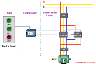
PLC Program for Forward and Reverse Motor control

3 Phase Motor Control using PLC Ladder Logic

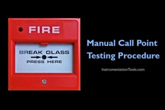
Manual Call Point Testing Procedure

Manual Call Point Testing Procedure

Linear Motion Control

What is Linear Motion Control? – Factors and Example Devices

3-Wire, Three-Phase Delta Wiring System

3-Wire, Three-Phase Delta Wiring System

Create PLC Program based on Logic Circuit

Create PLC Program based on Logic Circuit

Gamp 5 Compliance in Pharmaceutical Industry

What is Gamp 5 Compliance in Pharmaceutical Industry?

Normally closed input actuator as stop button.

Normally-Closed Contacts for Stop Buttons

Relay Internal Parts

Relay Operation, Types, Symbols & Characteristics

Menu

  • About
  • Privacy Policy
  • Copyright

Quick Links

  • Learn PLC
  • Helping Hand
  • Part Time Job

YouTube Subscribe

Follow US
All rights reserved. Reproduction in whole or in part without written permission is prohibited.
Welcome Back!

Sign in to your account

Username or Email Address
Password

Lost your password?