Inst ToolsInst ToolsInst Tools
  • Courses
  • Automation
    • PLC
    • Control System
    • Safety System
    • Communication
    • Fire & Gas System
  • Instrumentation
    • Design
    • Pressure
    • Temperature
    • Flow
    • Level
    • Vibration
    • Analyzer
    • Control Valve
    • Switch
    • Calibration
    • Erection & Commissioning
  • Interview
    • Instrumentation
    • Electrical
    • Electronics
    • Practical
  • Q&A
    • Instrumentation
    • Control System
    • Electrical
    • Electronics
    • Analog Electronics
    • Digital Electronics
    • Power Electronics
    • Microprocessor
  • Request
Search
  • Books
  • Software
  • Projects
  • Process
  • Tools
  • Basics
  • Formula
  • Power Plant
  • Root Cause Analysis
  • Electrical Basics
  • Animation
  • Standards
  • 4-20 mA Course
  • Siemens PLC Course
Reading: Eddy Current Working Principle Animation
Share
Font ResizerAa
Inst ToolsInst Tools
Font ResizerAa
  • Courses
  • Design
  • PLC
  • Interview
  • Control System
Search
  • Courses
  • Automation
    • PLC
    • Control System
    • Safety System
    • Communication
    • Fire & Gas System
  • Instrumentation
    • Design
    • Pressure
    • Temperature
    • Flow
    • Level
    • Vibration
    • Analyzer
    • Control Valve
    • Switch
    • Calibration
    • Erection & Commissioning
  • Interview
    • Instrumentation
    • Electrical
    • Electronics
    • Practical
  • Q&A
    • Instrumentation
    • Control System
    • Electrical
    • Electronics
    • Analog Electronics
    • Digital Electronics
    • Power Electronics
    • Microprocessor
  • Request
Follow US
All rights reserved. Reproduction in whole or in part without written permission is prohibited.
Inst Tools > Blog > Animation > Eddy Current Working Principle Animation

Eddy Current Working Principle Animation

Last updated: February 18, 2018 4:32 am
Editorial Staff
Animation How It Works
2 Comments
Share
1 Min Read
SHARE

Eddy Current Working Principle Animation

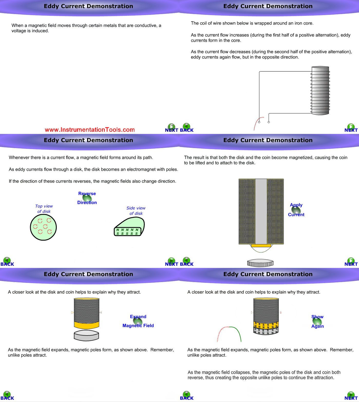
Eddy currents are currents induced in conductors, when a conductor is exposed to a changing magnetic field due to relative motion of the field source and conductor; or due to variations of the field with time. This can cause a circulating flow of electrons, or a current, within the body of the conductor. These circulating eddies of current have inductance and thus induce magnetic fields. These fields can cause repulsive, attractive,propulsion and drag effects. The stronger the applied magnetic field, or the greater the electrical conductivity of the conductor, or the faster the field changes, then the greater the currents that are developed and the greater the fields produced.

Eddy currents, like all electric currents, generate heat as well as electromagnetic forces. The heat can be harnessed for induction heating. The electromagnetic forces can be used for levitation, creating movement, or to give a strong braking effect. Eddy currents can also have undesirable effects, for instance power loss in transformers. In this application, they are minimized with thin plates, by lamination of conductors or other details of conductor shape.

Also Read: Open Loop & Closed Loop Animation
Don't Miss Our Updates
Be the first to get exclusive content straight to your email.
We promise not to spam you. You can unsubscribe at any time.
Invalid email address
You've successfully subscribed !

Continue Reading

Logic Gates Animation
Paddle Wheel Flow Meters – Principle, Advantages, Limitations
Animation of Electromagnetic Relay
Level Transmitter Animation
Deluge System for Transformer Protection Animation
Pushbutton switches and Types of Switches
Share This Article
Facebook Whatsapp Whatsapp LinkedIn Copy Link
Share
2 Comments
  • Manish says:
    February 6, 2019 at 12:58 am

    Very good and useful.

    Reply
  • Ramon Fernandez says:
    February 19, 2020 at 9:24 am

    Good explanations, thank, really useful

    Reply

Leave a Reply Cancel reply

Your email address will not be published. Required fields are marked *

Stay Connected

128.3kFollowersLike
69.1kFollowersFollow
210kSubscribersSubscribe
38kFollowersFollow

Categories

Explore More

Stepper Motor Working Principle
Types of Pneumatic Actuators Animation
Sight Glass Level Measurement Principle
Vibrating Fork Level Switch Working Animation
Deluge Valve Working Principle
Turbine Flow Meters Animation
Dome Valve Working Principle
Basics of Chromatograph Operation

Keep Learning

Piston Flow Meters Working Animation

Piston Flow Meters Working Principle with Animation

Transistor as Switch Working Animation

How a Transistor Switch Works

Flow Switch Principle

In-Line Flow Switch Working Principle and Animation

PTC NTC Thermistors Comparation

Thermistor Working Principle

Online Simulation

Catalytic-Bead-Sensor-2

Gas Detectors Working Principle

Pyrometer Principle

Optical Pyrometer Working Principle Animation

Displacer Operated Level Switch Working Principle

Displacer Level Switch Working Principle

Learn More

Field Instruments

Is Vacuum affects Field Instruments in Industries?

Wellhead Control Panel

Basics of Wellhead Control Panel (WHCP)

Flow meter Turndown Ratio

Importance of Flow Meter Turndown Ratio

PID Controller Functionality

PID Controller Theory

Under and Over-Capacity Control Valve

Under and Over-Capacity Control Valve Pose Poor Controllability

Loop Current Step Response (LCSR) Test for RTD

Response Time Test of RTD and Thermocouple

Steam Pressure Taps Primary Block Valves Glands and Bonnets Leaks

Instrument Steam Pressure Taps Primary Block Valves Glands and Bonnets Leaks

Electrical Machines Questions and Answers

Induction Motor Phasor Diagram

Menu

  • About
  • Privacy Policy
  • Copyright

Quick Links

  • Learn PLC
  • Helping Hand
  • Part Time Job

YouTube Subscribe

Follow US
All rights reserved. Reproduction in whole or in part without written permission is prohibited.
Welcome Back!

Sign in to your account

Username or Email Address
Password

Lost your password?