Resistance is a very important parameter in electrical engineering. According to Ohm’s law it defines how it can resist the flow of current in a circuit. So it matters a lot when it is required to pass only the required amount of current in a circuit. When it comes to resistance, two terms often come to mind – earth and insulation. Both are very important terms to understand for electrical engineers. In them, resistance plays a very important part. Both have a resistance, but differ in terms of functionality. In this post, we will see the difference between the earth resistance and insulation resistance.
What is Earth Resistance?
Every electrical circuit has a leakage current or fault current flowing through it. This fault current is dangerous for the system as it can damage the circuit. So, such fault currents must be safely dissipated to a certain path. In electrical systems, this path is called an earth pit. A wire is used to carry this leakage current to the earth pit. This wire is called an earthing conductor. The role of this conductor is to allow the passage of leakage current safely to the main ground or earth pit. Due to this, the electrical system remains safe from any damage.
Now, as this conductor is intended to carry the leakage current, it must allow a very minimum resistance. If the resistance is greater, then the current will not be able to pass through it. Then it will be of no use for the earth conductor in the system, as it will not allow the leakage current to pass through it, which will damage the system. So, the earth resistance is defined as the resistance offered by the earth conductor to the leakage current. The value must typically be between 0.5 – 1 ohms, so that leakage or old current is allowed to pass easily.
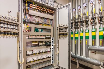
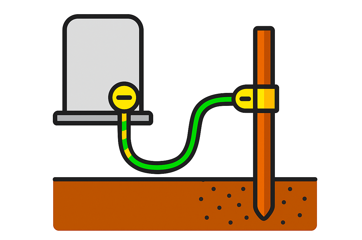
Refer to the image below for understanding the Earth connection. As shown, a wire is connected from the electrical panel to the earth pit. Leakage current flows through a metal body, so it is connected to the panel body.
What is Insulation Resistance?
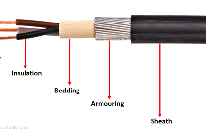
Every electrical cable has insulation with some dielectric strength so that the current does not leak from inside the conductor to the outside world. Due to this insulation, if you touch the live cable, you will not get an electric shock. You cannot practically layer cable with only conductors inside. It will short the other wires in contact nearby or cause an electric shock to the person who touches the wire. So the insulation is some non-conducting material that blocks the flow of current through it. It is mostly made of PVC, XLPE (cross-linked polyethylene), or rubber.
As this resistance is intended to block the flow of current, it must be of a higher value. If the resistance is less, then the current will be able to pass through it. Then it will be of no use for the insulation in the cable, as it will allow the current to pass through it and come in contact with the outside environment, making it dangerous. So, the insulation resistance is defined as the resistance offered by the insulator to the current.
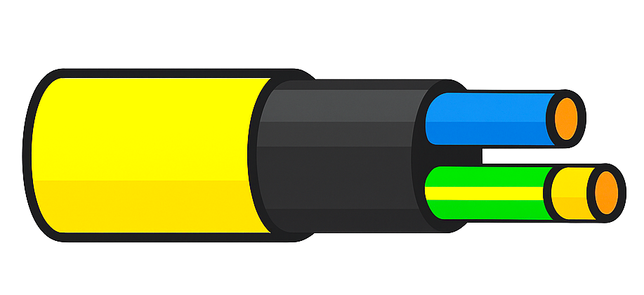
Refer to the image below for understanding insulation. As shown, the insulator (yellow color) is spread in the outermost layer of the wire, which covers the internal conductor (blue color), thus preventing the flow of current through its body.
Comparison between insulation resistance and earth resistance
- Earthing resistance is intended to allow the flow of leakage current into the ground, whereas an insulation resistance is intended to block the flow of current between conductors or between the conductor and earth.
- Earthing resistance can be measured using a simple multimeter, whereas insulation resistance is measured using a Megger or insulation resistance tester. A test voltage of 500 – 1000 V DC is applied in a Megger to measure the resistance values.
- Earthing resistance is of a very small value, which is typically between 1-5 ohms, whereas insulation resistance is in megohms. It is to be noted that even small wires of 2 square mm can have resistances in megaohms. This is because the insulating materials are designed with a very high IR (insulation resistance) rating.
- Earthing resistance is measured between the earth conductor starting points and the main earthing pit. Insulation resistance is measured between phase to earth, or phase to phase, or even phase to neutral.
- Factors which affect ground resistance are soil moisture, texture, the size of the earthing conductor, its shape, and the trench where the earthing pit is dug. Factors which affect insulation resistance are moisture, temperature, mechanical damage, the voltage the cable is carrying, cable length, and insulation material type.
To summarise our topic, let us see the points in short discussed:
- Earth resistance is used to measure the resistance of the earthing conductor, which is connected to the main earth pit.
- Insulation resistance is used to measure the resistance of the insulator, which is layered over the outermost body of the cable.
- Earth resistance is intended to allow the flow of current, whereas insulation resistance is intended to block the flow of current. So, the earth resistance must be of a minimal value, whereas the insulation resistance must be of a higher value.
Read Next:
- IEC 60909 and IEC 61363 for Short Circuit
- Circuit Breaker versus Disconnector
- Automatic Transfer Switch Circuit
- Continuity of Protective Conductors
- Emergency STOP vs Emergency Power OFF