Inst ToolsInst ToolsInst Tools
  • Courses
  • Automation
    • PLC
    • Control System
    • Safety System
    • Communication
    • Fire & Gas System
  • Instrumentation
    • Design
    • Pressure
    • Temperature
    • Flow
    • Level
    • Vibration
    • Analyzer
    • Control Valve
    • Switch
    • Calibration
    • Erection & Commissioning
  • Interview
    • Instrumentation
    • Electrical
    • Electronics
    • Practical
  • Q&A
    • Instrumentation
    • Control System
    • Electrical
    • Electronics
    • Analog Electronics
    • Digital Electronics
    • Power Electronics
    • Microprocessor
  • Request
Search
  • Books
  • Software
  • Projects
  • Process
  • Tools
  • Basics
  • Formula
  • Power Plant
  • Root Cause Analysis
  • Electrical Basics
  • Animation
  • Standards
  • 4-20 mA Course
  • Siemens PLC Course
Reading: Differential Pressure (DP) Level transmitter Installed Below Tapping Point
Share
Font ResizerAa
Inst ToolsInst Tools
Font ResizerAa
  • Courses
  • Design
  • PLC
  • Interview
  • Control System
Search
  • Courses
  • Automation
    • PLC
    • Control System
    • Safety System
    • Communication
    • Fire & Gas System
  • Instrumentation
    • Design
    • Pressure
    • Temperature
    • Flow
    • Level
    • Vibration
    • Analyzer
    • Control Valve
    • Switch
    • Calibration
    • Erection & Commissioning
  • Interview
    • Instrumentation
    • Electrical
    • Electronics
    • Practical
  • Q&A
    • Instrumentation
    • Control System
    • Electrical
    • Electronics
    • Analog Electronics
    • Digital Electronics
    • Power Electronics
    • Microprocessor
  • Request
Follow US
All rights reserved. Reproduction in whole or in part without written permission is prohibited.
Inst Tools > Blog > Instrumentation Tools > Differential Pressure (DP) Level transmitter Installed Below Tapping Point

Differential Pressure (DP) Level transmitter Installed Below Tapping Point

Last updated: November 12, 2019 3:34 pm
Editorial Staff
Instrumentation Tools Level Measurement
10 Comments
Share
1 Min Read
SHARE
Open Tank Level Measurement (Single Seal Application) Transmitter installed below Tapping Point
Level Measurement Installed Below Tapping Point for Open Tank
This calculation used for open tank level measurement with transmitter installed below tapping point

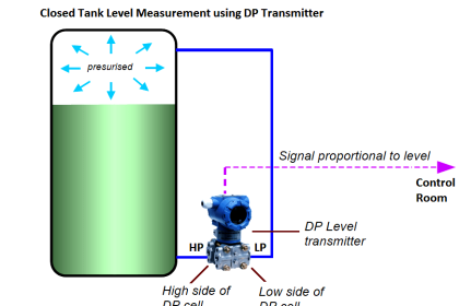
The formulas for calculating transmitter URV and LRV are as follows:

HP Side or LRV or Transmitter 0% = Hmin.S1 + X.S2

LP Side or URV or Transmitter 100% = Hmax.S1 + X.S2

Where

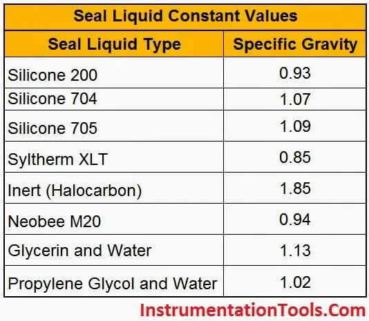
S1 = Specific gravity of tank liquid.
S2 = Specific gravity of seal liquid.
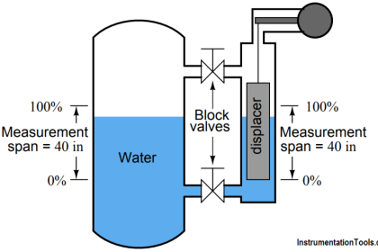
Hmin = Equivalent head of water at minimum level.
Hmax = Equivalent head of water at maximum level.
X = Distance between transmitter and tapping point.

NOTE:

1. The Parameters H,X can be entered in any units like mmh20, inh20 but must be same

2. If you are using direct tubing from tapping point to transmitter without filling any additional liquid (Like water) that means you are not using any special seal liquid, so S2=S1, Here Specific gravity of Process liquid only considers for both S1 & S2. Hence S1=S2.

The Following tables specifies the seal liquid constant values:

Seal-Liquid-Constants

Don't Miss Our Updates
Be the first to get exclusive content straight to your email.
We promise not to spam you. You can unsubscribe at any time.
Invalid email address
You've successfully subscribed !

Continue Reading

Non Contacting Radar Level Transmitter Animation
Displacer Level Transmitter Dry Calibration with Weights
Effect of Temperature & Pressure on Level Measurement
Why Measure Level
Magnetic Level Indicator Principle, Limitations, Installation and Calibration
Calculate Current (4-20ma) from Process variable PV
Share This Article
Facebook Whatsapp Whatsapp LinkedIn Copy Link
Share
10 Comments
  • Agarwal M V says:
    April 18, 2015 at 10:06 am

    Fast calculation…..Excellent

    Reply
  • antalya masozleri says:
    August 18, 2015 at 8:11 am

    Superb, what a web site it is! This web site presents useful data to us,
    keep it up.

    Reply
  • Senthil RK says:
    September 30, 2015 at 10:07 am

    I really like this website It is very useful to us

    Reply
    • S Bharadwaj Reddy says:
      September 30, 2015 at 4:11 pm

      Thank you all for the supporting comments.

      Reply
  • raghava reddy says:
    January 21, 2016 at 4:19 pm

    i like it our website…………….raghava reddy

    Reply
  • syahiran says:
    February 10, 2016 at 5:24 pm

    Sory sir..i am confuse..Before i learn about formula p×g×h..
    But in ur formula for wet leg and dry leg not use..sory sir..i new technician in instrument..i just want to learn more..tq

    Reply
  • Ques says:
    February 17, 2016 at 2:08 pm

    Hey! Someone in my Facebook group shared this website with us so I came to look it over. I’m definitely loving the information.
    Exceptional blog and terrific style and design.

    Reply
  • abhishek raj says:
    July 10, 2018 at 4:40 pm

    how to convert mmh2o to m3/hr ?

    Reply
    • azetou says:
      July 10, 2018 at 8:26 pm

      Hi, mmH2O is a unit for pressure and m3/hr is a unit for flow, I assume your question is related to differential pressure (D/P) type flow measurement where the flow is proportional to the square root of the pressure loss across the D/P flow element (ex : orifice plate).

      Reply
      • azetou says:
        July 10, 2018 at 8:32 pm

        Check out this article : https://instrumentationtools.com/square-root-characteristics-of-differential-pressure-flow-meters/

        Reply

Leave a Reply Cancel reply

Your email address will not be published. Required fields are marked *

Stay Connected

128.3kFollowersLike
69.1kFollowersFollow
210kSubscribersSubscribe
38kFollowersFollow

Categories

Explore More

Capacitive Level Switch Principle
Wrong Installation of Horn Type Radar Level Transmitter on Sloping Tank
Capacitive Level Measurement
Level Measurement Objective Questions
Guided-Wave Radar Instruments Diagnostics
Level Troll working principle
Hydrostatic Tank Gauging (HTG)
Vibrating Fork Level Switch Working Animation

Keep Learning

Closed Tank Level Measurement Formula

Siemens Differential Pressure Transmitter Calculations (Flange Type)

Open Tank Interface Level measurement principle

Open Tank Interface Level Measurement

Float Level Switch Principle

Float Level Switch Working Principle Animation

Hydrostatic interface level measurement Formula

Hydrostatic Interface Level Measurement

Sounding Level Transmitter Working Animation

Instrumentation Impulse Lines

All About Instrumentation Impulse Lines

Installation and Calibration of Level Transmitter

Installation and Calibration of Level Transmitter

Density-Measurement-using-DP-Transmitter-for-Closed-Tank-Wet-leg

Density Measurement using DP Transmitter for closed tank with wet leg

Learn More

Level Measurement Objective Questions

Level Measurement Objective Questions

Orifice Construction

How does an Orifice Measures Flow?

Mechanical Vibration Switch

Vibration Switch Working Principle

Tank uses 3 Pressure Transmitters to Measure Level & Density

Tank uses 3 Pressure Transmitters to Measure Level & Density

Optimal Control Systems

Optimal Control Problems – Part 1

Siemens PLC programming: BCD, Integer, Double Integer, Real

Thermodynamic cycle

Thermodynamic Cycles in Power Plant

RTD with Thermowell

Temperature Sensor Accessories

Menu

  • About
  • Privacy Policy
  • Copyright

Quick Links

  • Learn PLC
  • Helping Hand
  • Part Time Job

YouTube Subscribe

Follow US
All rights reserved. Reproduction in whole or in part without written permission is prohibited.
Welcome Back!

Sign in to your account

Username or Email Address
Password

Lost your password?