Inst ToolsInst ToolsInst Tools
  • Courses
  • Automation
    • PLC
    • Control System
    • Safety System
    • Communication
    • Fire & Gas System
  • Instrumentation
    • Design
    • Pressure
    • Temperature
    • Flow
    • Level
    • Vibration
    • Analyzer
    • Control Valve
    • Switch
    • Calibration
    • Erection & Commissioning
  • Interview
    • Instrumentation
    • Electrical
    • Electronics
    • Practical
  • Q&A
    • Instrumentation
    • Control System
    • Electrical
    • Electronics
    • Analog Electronics
    • Digital Electronics
    • Power Electronics
    • Microprocessor
  • Request
Search
  • Books
  • Software
  • Projects
  • Process
  • Tools
  • Basics
  • Formula
  • Power Plant
  • Root Cause Analysis
  • Electrical Basics
  • Animation
  • Standards
  • 4-20 mA Course
  • Siemens PLC Course
Reading: Differential Pressure (DP) Level transmitter Installed Above Tapping Point
Share
Font ResizerAa
Inst ToolsInst Tools
Font ResizerAa
  • Courses
  • Design
  • PLC
  • Interview
  • Control System
Search
  • Courses
  • Automation
    • PLC
    • Control System
    • Safety System
    • Communication
    • Fire & Gas System
  • Instrumentation
    • Design
    • Pressure
    • Temperature
    • Flow
    • Level
    • Vibration
    • Analyzer
    • Control Valve
    • Switch
    • Calibration
    • Erection & Commissioning
  • Interview
    • Instrumentation
    • Electrical
    • Electronics
    • Practical
  • Q&A
    • Instrumentation
    • Control System
    • Electrical
    • Electronics
    • Analog Electronics
    • Digital Electronics
    • Power Electronics
    • Microprocessor
  • Request
Follow US
All rights reserved. Reproduction in whole or in part without written permission is prohibited.
Inst Tools > Blog > Instrumentation Tools > Differential Pressure (DP) Level transmitter Installed Above Tapping Point

Differential Pressure (DP) Level transmitter Installed Above Tapping Point

Last updated: November 12, 2019 3:34 pm
Editorial Staff
Instrumentation Tools Level Measurement
11 Comments
Share
1 Min Read
SHARE
Open Tank Level Measurement (Single Seal Application) Transmitter installed above Tapping Point
Differential Pressure (DP) Level transmitter Installed Above Tapping Point
This calculation used for open tank level measurement with transmitter installed above tapping point

The formulas for calculating transmitter URV and LRV are as follows:

HP Side or LRV or Transmitter 0% = Hmin.S1 – X.S2

LP Side or URV or Transmitter 100% = Hmax.S1 – X.S2

Where

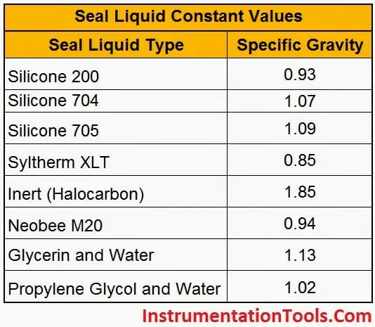
S1 = Specific gravity of tank liquid.
S2 = Specific gravity of seal liquid.
Hmin = Equivalent head of water at minimum level.
Hmax = Equivalent head of water at maximum level.
X = Distance between transmitter and tapping point.

NOTE:

1. The Parameters H,X can be entered in any units like mmh20, inh20 but must be same

2. If you are using direct tubing from tapping point to transmitter without filling any additional liquid (Like water) that means you are not using any special seal liquid, so S2=S1, Here Specific gravity of Process liquid only considers for both S1 & S2. Hence S1=S2.

The Following tables specifies the seal liquid constant values:

Capillary-Seal-Liquid-Constants

Don't Miss Our Updates
Be the first to get exclusive content straight to your email.
We promise not to spam you. You can unsubscribe at any time.
Invalid email address
You've successfully subscribed !

Continue Reading

Level Troll working principle
How a Level Switch Works
What is the Simple Alternative Vessel Level Indication?
Basics of Differential Pressure Level Transmitters
What are Mechanical Level Indicators? – Classification & Principle
Basics of DP Transmitter Suppression and Elevation
Share This Article
Facebook Whatsapp Whatsapp LinkedIn Copy Link
Share
11 Comments
  • Anupam says:
    April 18, 2015 at 6:44 am

    Its a wonderful tool.
    It takes less than 2 minutes to calculate the instrument range.
    Thanks
    Anupam

    Reply
  • arun says:
    May 19, 2015 at 8:38 am

    pls post procedure for calibration closed tank dp level transmitter

    Reply
    • S Bharadwaj Reddy says:
      May 20, 2015 at 4:23 pm

      Hi Arun,
      Thanks for the comment. Closed tank DP level transmitter dry & wet leg calibration procedures available here
      https://instrumentationtools.com/closed-tank-dp-type-level-measurement-with-dry-leg-and-transmitter-installed-below-tapping-poin/
      https://instrumentationtools.com/closed-tank-dp-type-level-measurement-with-wet-leg-and-transmitter-installed-below-tapping-poin/
      Thanks,
      S Bharadwaj Reddy

      Reply
  • Mohammad sultan Taj says:
    December 16, 2015 at 1:10 pm

    Mr Bhardwaj Reddy you have done very good job,
    Manchi pani chesaru

    Reply
  • arjun says:
    December 29, 2015 at 1:53 pm

    Closed Tank DP Type Level Measurement with wet leg and transmitter installed above tapping point is it possible

    Reply
    • S Bharadwaj Reddy says:
      December 29, 2015 at 2:33 pm

      Definitely Yes, Possible. But in the above figure it is shown the transmitter installed above the tank i.e. only for understanding purpose. In Practice, the transmitter installed just above tapping point only not above the tank. Thanks

      Reply
  • Pravin says:
    January 7, 2016 at 4:12 pm

    Good Info……Keep it uP…

    Reply
  • vijay says:
    February 18, 2016 at 7:45 am

    thank sir,it very usefull sir,
    closed tank level tx install below& above tapping point

    Reply
  • jaya says:
    May 11, 2016 at 7:51 am

    great job sir, great indian app

    Reply
  • Qurban Ansari says:
    August 8, 2016 at 4:41 pm

    Dear Sir, Can you explain me how to Calibrate Transmitter like FT PT LT in very easy way.

    Reply
  • MINESHKUMAR says:
    April 28, 2018 at 3:25 pm

    HI MR. S BHARADWAJ REDDY, GOOD AFTERNOON AND GREETING,

    WILL YOU PLEASE MASG ME ERS(ELECTRONIC REMOTE SENSOR ) TYPE LEVEL TXM, ITS INSTALLED AT FIRST PLATFORM OF DRUM. ITS BEFORE GOOD WORKING NOW, ITS START PROBLEM. HART NOT CONNECT AND DEVICE ALWAYS SHOW DEVICE NOT FOUND, TXM DISPLAY SHOW. WHEN EVER WE CONNECT HART.

    WILL YOU PLEASE GIVE ME ANY SOLUTION . ALL WIRE AND EARTHING IS GOOD, NO WIRE CUT ALSO. PANEL SITE ALSO GOOD, JB WIRE ALSO GOOD.

    Reply

Leave a Reply Cancel reply

Your email address will not be published. Required fields are marked *

Stay Connected

128.3kFollowersLike
69.1kFollowersFollow
210kSubscribersSubscribe
38kFollowersFollow

Categories

Explore More

Magnetic Level Indicator Principle, Limitations, Installation and Calibration
Effect of Tank Design on Accuracy of Level Measurement
Density Measurement for Open Tank with Constant Level Application
Micro-impulse Level Transmitter Principle
Transmitter Current Conversion Tool
RTD Calculator : Calculate Resistance from Temperature
Types of Tank Gauging Level Measurement Systems
Convert Linear mA to Square root mA

Keep Learning

Practical Level Sensors Questions and Answers

Practical Level Sensors Questions and Answers

Installation and Calibration of Level Transmitter

Installation and Calibration of Level Transmitter

Non-Contacting-Radar-Level-Transmitter-Animation

Non Contacting Radar Level Transmitter Animation

Density-Measurement-using-DP-Transmitter-for-Closed-Tank-Wet-leg

Density Measurement using DP Transmitter for closed tank with wet leg

Wet Leg Level Transmitter

Basics of DP Level Measurement

Zero Suppression in level Measurement

Zero Suppression and Zero Elevation Calculations

Weight-based Level Instruments Principle

Weight-based Level Measurement Principle

Nuclear Level Measurement

Nuclear Level Detectors Cascade or Master/Slave concept

Learn More

Instrumentation Bulk Material

Instrumentation Bulk Material Requirements in Oxygen Service

Shunt-Wound DC Generator Principle

Shunt-Wound DC Generators

Control Valves Basic Theory

Control Valves Theory

Typical Switchyard Layout

Electrical Substation – Busbar Arrangements and Layouts

Positive Displacement Pumps

What are Positive Displacement Pumps and their Types?

PLC Instruction List Code

PLC Instruction List Program for Basic Instructions

VFD Commissioning and Testing Procedure

VFD Commissioning and Testing Procedure (Variable Frequency Drive)

Electronic Devices & Circuits Objective Questions

Electronic Devices & Circuits Quiz – Set 5

Menu

  • About
  • Privacy Policy
  • Copyright

Quick Links

  • Learn PLC
  • Helping Hand
  • Part Time Job

YouTube Subscribe

Follow US
All rights reserved. Reproduction in whole or in part without written permission is prohibited.
Welcome Back!

Sign in to your account

Username or Email Address
Password

Lost your password?