By using this site, you agree to the Privacy Policy and Terms of Use.
Accept
Inst ToolsInst ToolsInst Tools
  • Ask
  • Courses
  • Videos
  • Q & A
    • Interview
      • Instrumentation
      • Electronics
      • Electrical
      • Practical Questions
    • MCQ
      • Instrumentation MCQ
      • Electrical MCQ
      • Electronics MCQ
      • Control Systems MCQ
      • Analog Electronics MCQ
      • Digital Electronics MCQ
      • Power Electronics MCQ
      • Microprocessor MCQ
      • Multiple Choice Questions
  • EE
    • Electronics
      • Electronics Q & A
      • Electronic Basics
      • Electronic Devices & Circuits
      • Electronics Animation
      • Digital Electronics
    • Electrical
      • Electrical Basics
      • Electrical Q & A
      • Power Electronics
      • Electrical Machines
      • Electrical Animation
      • Power Systems
      • Switchgear & Protection
      • Transmission & Distribution
  • Measure
    • Control Valves
    • Calibration
    • Temperature
    • Pressure
    • Flow
    • Level
    • Analyzers
    • Switches
    • Vibration
    • Solenoid Valve
  • Control
    • PLC Tutorials
    • Control Systems
    • Safety Instrumented System (SIS)
    • Communication
    • Fire & Gas System
  • More
    • Design
    • Tools
    • Animation
    • Basics
    • Formulas
    • Standards
    • TextBooks
    • Common
    • Software
    • Excel Tools
    • Erection & Commissioning
    • Process Fundamentals
    • Videos
    • Books
Search
All rights reserved. Reproduction in whole or in part without written permission is prohibited.
Reading: Digital Control Valve Working Principle
Share
Notification Show More
Font ResizerAa
Inst ToolsInst Tools
Font ResizerAa
  • Ask
  • Courses
  • Videos
  • Q & A
  • EE
  • Measure
  • Control
  • More
Search
  • Ask
  • Courses
  • Videos
  • Q & A
    • Interview
    • MCQ
  • EE
    • Electronics
    • Electrical
  • Measure
    • Control Valves
    • Calibration
    • Temperature
    • Pressure
    • Flow
    • Level
    • Analyzers
    • Switches
    • Vibration
    • Solenoid Valve
  • Control
    • PLC Tutorials
    • Control Systems
    • Safety Instrumented System (SIS)
    • Communication
    • Fire & Gas System
  • More
    • Design
    • Tools
    • Animation
    • Basics
    • Formulas
    • Standards
    • TextBooks
    • Common
    • Software
    • Excel Tools
    • Erection & Commissioning
    • Process Fundamentals
    • Videos
    • Books
Follow US
All rights reserved. Reproduction in whole or in part without written permission is prohibited.
Inst Tools > Blog > Control Valves > Digital Control Valve Working Principle

Digital Control Valve Working Principle

Last updated: March 21, 2019 11:13 pm
Editorial Staff
Control Valves
4 Comments
Share
5 Min Read
SHARE

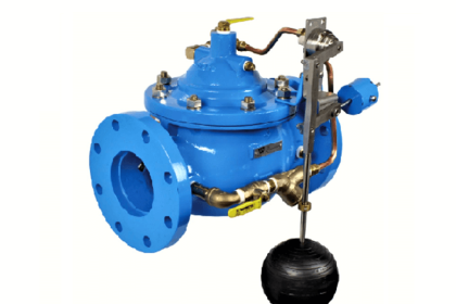
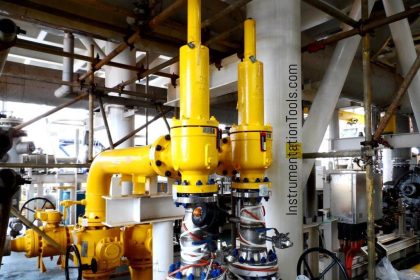
Diaphragm Digital Control Valve is an electrically actuated, hydraulically operated multi-function control valve. It can be used for local as well as remote controlled batching operations with electronic batch controller.

Contents
Digital Control ValveStage 1Stage 2Stage 3Stage 4Stage 5Stage 6Stage 7Articles You May Like :Control Valve Tips & TricksSizing the Control ValvesPneumatic Actuators TypesFlow Capacity of a ValveDome Valve Principle

The valve also offers an in-built flow governing function.

Digital Control Valve

Digital Control Valve Working Principle

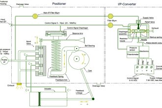
The Diaphragm Digital Control Valve basically consists of a diaphragm operated main valve and two solenoid valves.

Normally open (NO) solenoid connects the valve cover chamber to the upstream pressure, whereas normally closed (NC) solenoid connects the valve cover chamber to the downstream pressure.

When the Diaphragm Digital Control Valve is used with an electronic batch controller, it can be digitally controlled by operating the solenoid valves through any of these three stages :

  • when NO and NC solenoids are energized, the valve opens gradually.
  • when NC solenoid is de-energized (keeping NO solenoid energized), the valve locks at its current position.
  • when NO and NC solenoids are de-energized, the valve closes gradually.

The operation of the valve is simple and is explained below. The total batch quantity delivered and controlled through the valve is divided into 7 stages (Refer graph) for the purpose of convenience.

Digital Control Valve Operation

Initially both NO and NC solenoid valves are in deenergised condition. The NO valve applies high upstream pressure on the diaphragm, whereas the NC valve prevents this pressure from getting drained to the downstream side.

The valve remains close as a result of this.

Digital Control Valve Principle

Stage 1

Both NO and NC solenoids are energized. NO valve now restricts the high upstream pressure from entering into the cover chamber. NC valve permits the pressure above the diaphragm to vent to the low downstream pressure.

This creates a differential pressure across the diaphragm, the high upstream pressure acting from below the diaphragm opens the main valve and allows the flow to start through the valve.

Stage 2

As the flow rate reaches predefined value (set in the batch controller as “Low Flow Start”) the NC valve is de-energized.

This prevents further draining of the chamber and locks the valve at this flow rate. Initial delivery at slow speed avoids splashing of product and also avoids the generation of static charge.

Stage 3

When sufficient quantity is delivered at the slow speed, the NC valve is energized again. This allows further draining of the chamber and hence increases the flow.

Stage 4

When the flow reaches to the maximum level (set in the batch controller), the NC solenoid is de-energized. This maintains the constant high flow rate for the remaining batch.

During this stage, the flow rate control is done by the batch controller. When a number of flow meters are connected to the same pump, stopping (or starting) one or more meters increases (or decreases) the flow rate at the remaining meters.

When the flow rate increases, the NO solenoid is de-energized momentarily. This injects some high pressure in the cover chamber and makes the valve to throttle in order to maintain the set flow rate.

If the flow rate decreases, the NC solenoid is energized momentarily. This allows slight draining of the chamber and allows the valve to open further in order to maintain the set flow rate.

Stage 5

At the end of the batch, the NO solenoid is de-energized. This injects high upstream pressure into the cover chamber and throttles the valve.

Stage 6

When the valve throttles sufficiently to achieve the predefined slow closing flow rate (set in the batch controller), the NO solenoid is energized. This maintains the uniform flow rate.

Stage 7

When the batch quantity is delivered, the NO solenoid is de-energized. (NC solenoid is already de-energized.) This applies high upstream pressure into the cover chamber, which makes the main valve to close completely to achieve bubble-tight shut-off.

Note : The number of stages during opening and closing are programmed in the batch controller and can be as many as desired. One stage during opening and two during closing are recommended.

Caution : Sufficient pumping flow rate should be available to achieve the flow parameters set in the electronic batch controller. In the absence of this, there are chances of delayed response in closure, resulting in valve over-run.

Articles You May Like :

Control Valve Tips & Tricks

Sizing the Control Valves

Pneumatic Actuators Types

Flow Capacity of a Valve

Dome Valve Principle

Don't Miss Our Updates
Be the first to get exclusive content straight to your email.
We promise not to spam you. You can unsubscribe at any time.
Invalid email address
You've successfully subscribed !
How-to do Control Valve Calibration?
Types of Check Valves
Troubleshooting Common Control Valve Problems
List of Valve Standards
Electrical Actuators
Share This Article
Facebook Whatsapp Whatsapp LinkedIn Copy Link
Share
4 Comments
  • angelo fabillar says:
    October 21, 2017 at 8:41 am

    HI i want to download this topic DIGITAL CONTROL VALVES WORKING PRINCIPLE. how to get a copy of this.

    Reply
    • S Bharadwaj Reddy says:
      October 21, 2017 at 9:22 am

      Hi, Use Print option available at bottom of the article. click it and save in pdf.

      Reply
  • Saurav kumar says:
    March 10, 2021 at 12:02 am

    How to rectify the below mention problem ? , when batch start slow flow is very low i.e 5-30 min/lit this prevail for 300 lit and this flow is fluctuating and our system is shaking and same thing happen when low flow is there when our batch is to end i.e last 300 lit. Any one suggest which components are faulty , i have changed NC and NO solenoid but still face same issues.

    Reply
  • Kutu says:
    July 10, 2021 at 11:12 am

    I would asking, how to maintain pressure on downstream especially if the liquid is LPG, and at the end of down stream is coupling gas (NC). Is DCV has a way to reduce the pressure from downstream to upstream?

    Reply

Leave a Reply Cancel reply

Your email address will not be published. Required fields are marked *

Stay Connected

128.3kFollowersLike
69.1kFollowersFollow
208kSubscribersSubscribe
38kFollowersFollow

Recent Comments

  • MIHARITSOA Aina Sitraka on Top Non-PLC Certification Courses for Automation Professionals
  • Vaishnavi on Free Instrumentation Course for Trainee Engineers
  • anuj kapoor on DCS Program to Maintain Draft in Furnace
  • anuj kapoor on IoT based Smart Boiler Control System with Cloud PLC and SCADA

Related Articles

Valve Technician Interview Questions

Valve Technician Interview Questions

Piston Check Valve

What is Piston Check Valve ?

Steam conditioning valves

Concept of Steam Conditioning Valves

Pneumatic Piping Design and Specification

Pneumatic Piping Design and Specification

Purpose of Isolation valve

What are Isolation valves? – Purpose, Types, Configurations

cavitation-control valve trim

What is Control Valve Cavitation ?

Valve Interlock

Valve Interlock

Opposite Acting Valves

What is Split Range Control Loop ?

More Articles

Address Overlapping in Tia Portal

How to Check Address Overlapping in Tia Portal?

The Hardware Structure of DCS

DCS Applications and Hardware Structure of Plant Automation

Wireless HART Transmitter

How to Commission WirelessHART Transmitter With Gateway

Basic Logic Gate Symbols

Engineering Logic Diagrams

Control Speed of an Induction Motor using Analog Output of PLC

Control Speed of Induction Motor using Analog Output of PLC

Transmission Lines Protection Questions Answers

Transmission Lines Protection Questions Answers

Siemens Process Mode

Test and Process Modes in Siemens PLC

Bio Sensors Objective Questions

Bio Sensors Objective Questions

Follow US
All rights reserved. Reproduction in whole or in part without written permission is prohibited.
Welcome Back!

Sign in to your account

Username or Email Address
Password

Lost your password?