Inst ToolsInst ToolsInst Tools
  • Ask
  • Courses
  • Videos
  • Q & A
    • Interview
      • Instrumentation
      • Electronics
      • Electrical
      • Practical Questions
    • MCQ
      • Instrumentation MCQ
      • Electrical MCQ
      • Electronics MCQ
      • Control Systems MCQ
      • Analog Electronics MCQ
      • Digital Electronics MCQ
      • Power Electronics MCQ
      • Microprocessor MCQ
      • Multiple Choice Questions
  • EE
    • Electronics
      • Electronics Q & A
      • Electronic Basics
      • Electronic Devices & Circuits
      • Electronics Animation
      • Digital Electronics
    • Electrical
      • Electrical Basics
      • Electrical Q & A
      • Power Electronics
      • Electrical Machines
      • Electrical Animation
      • Power Systems
      • Switchgear & Protection
      • Transmission & Distribution
  • Measure
    • Control Valves
    • Calibration
    • Temperature
    • Pressure
    • Flow
    • Level
    • Analyzers
    • Switches
    • Vibration
    • Solenoid Valve
  • Control
    • PLC Tutorials
    • Control Systems
    • Safety Instrumented System (SIS)
    • Communication
    • Fire & Gas System
  • More
    • Design
    • Tools
    • Animation
    • Basics
    • Formulas
    • Standards
    • TextBooks
    • Common
    • Software
    • Excel Tools
    • Erection & Commissioning
    • Process Fundamentals
    • Videos
    • Books
Search
All rights reserved. Reproduction in whole or in part without written permission is prohibited.
Reading: Difference between Timer and Counter – PLC Basics
Share
Notification Show More
Font ResizerAa
Inst ToolsInst Tools
Font ResizerAa
  • Courses
  • PLC Tutorials
  • Control Systems
Search
  • Ask
  • Courses
  • Videos
  • Q & A
    • Interview
    • MCQ
  • EE
    • Electronics
    • Electrical
  • Measure
    • Control Valves
    • Calibration
    • Temperature
    • Pressure
    • Flow
    • Level
    • Analyzers
    • Switches
    • Vibration
    • Solenoid Valve
  • Control
    • PLC Tutorials
    • Control Systems
    • Safety Instrumented System (SIS)
    • Communication
    • Fire & Gas System
  • More
    • Design
    • Tools
    • Animation
    • Basics
    • Formulas
    • Standards
    • TextBooks
    • Common
    • Software
    • Excel Tools
    • Erection & Commissioning
    • Process Fundamentals
    • Videos
    • Books
Follow US
All rights reserved. Reproduction in whole or in part without written permission is prohibited.
Inst Tools > Blog > PLC Tutorials > Difference between Timer and Counter – PLC Basics

Difference between Timer and Counter – PLC Basics

In this article, we will learn the difference between timer and counter in PLC programming and understand the basic concepts.

Last updated: June 16, 2023 1:32 pm
Viral Nagda
PLC Tutorials
No Comments
Share
7 Min Read
SHARE

When you develop a PLC logic, you always need timers and counters. Any cycle in an automation process is generally incomplete without the use of timers and counters. You need them to execute a task after a certain time or keep the task on / off for a certain time. Its use depends on the application to be developed.

Contents
What is a Timer?What is a Counter?Difference between Timer and Counter

And, before going deeply into advanced instructions of PLC, a programmer must first understand these basic blocks to implement them properly and to get assistance in learning the advanced blocks more easily.

In this article, we will learn the difference between timers and counters in PLC programming.

What is a Timer?

A timer is an instruction that is used to turn on or off an output after a certain delay. For example, if you want to turn on a lamp after 5 seconds, then use a timer to execute this task.

A timer will take an input and when the input turns on, then its timing will start. After the time of 5 seconds elapses, then the timer output will turn on which turns on the lamp indirectly. This we are talking about is the normal timer on the type.

A timer has more two types – timer off and pulse timer. In short, the basic function is the same – execute a task after a certain delay.

Difference between Timer and Counter - PLC Basics

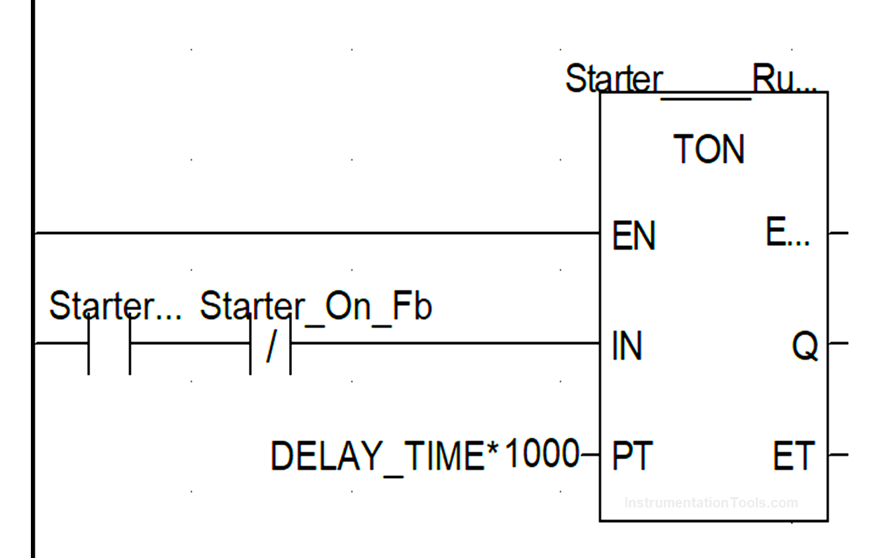
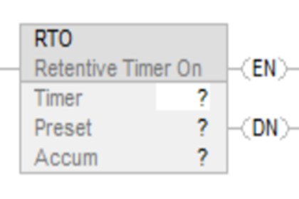
Refer to the above image for understanding more correctly. A timer has four inputs and outputs – input, set value, current value, and output. An input takes the condition for starting a timer, a set value is used to take the set timer value, the current value shows the current timer value running and the output is used to turn on or off the variable connected to it.

When the PLC timer gets the input and if the set value is 5 seconds, the timer starts as 1, 2, and 3, and so on till 5. When 5 seconds have been completed, the output turns on. When the input goes off, the timer’s current value immediately goes to zero.

Whether the timer was running or not; if the input is off, then the timer will not start and its output and current value will be zero. This is the functioning of a TON (timer on delay) timer.

What is a Counter?

A counter is an instruction that is used to turn on an output after a set count has been reached. The count can either increment or decrement.

For example, if you want to turn on a lamp after a push button has been pressed five times, then use a counter to execute this task. A counter will take an input and when the input turns on, then its count will increment to 1.

When the input goes off, nothing will happen. When it again receives the input, the count will increment to 2. After the count of 5 elapses, then the counter output will turn on which turns on the lamp indirectly. This we are talking about is the counter-up type.

A counter has one more type – counter down. In short, the basic function is the same – execute a task after a certain count.

PLC Tutorials - Timers and Counters

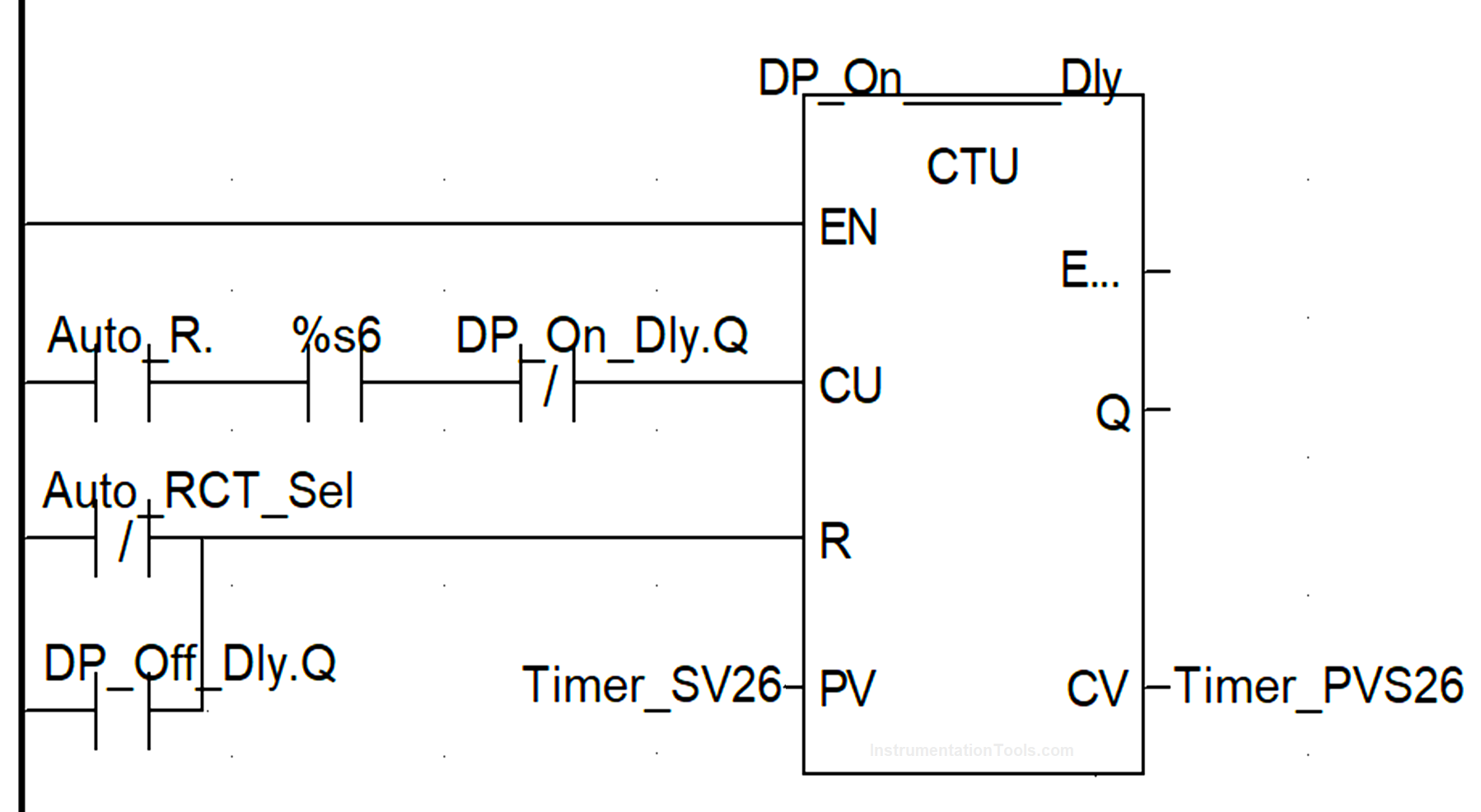
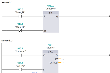
Refer to the above image for understanding more correctly. A counter has five inputs and outputs – count input, reset input, set value, current value, and output. A count input takes the condition for counting, reset input takes the condition for resetting the counter, the set value is used to take the set counter value, the current value shows the current counter value running and the output is used to turn on or off the variable connected to it.

When the counter gets the count input and if the set value is 5, the counter increments to 1 and so on till 5; at the receipt of each pulse in the count input (means the count input will have to be turned on and off 5 times). When 5 counts have been completed, the output turns on.

Now, even if the count input pulse is given, the counter will go on increasing after 5 and the output too will remain on. To again bring back the counter state to zero, you have to give reset input. When this input is given, the counter current value becomes zero and the output too turns off. So, it is similar to latching-type functioning. To unlatch the counter, you will have to reset it. This is the functioning of a CTU (count up) counter.

Difference between Timer and Counter

The main differences between timers and counters in a PLC are as follows.

  1. A timer needs to have its input continuously for turning on a variable, but a counter need not to have its input continuously. So, a timer works on continuous conditions, whereas a counter works on pulse conditions.
  2. If the timer input is removed, then its output will go back to zero states; but if the counter input is removed, then to the counter will hold its last value.
  3. A timer does not have reset input, whereas a counter requires reset input to get back the counter to its original state.
  4. The types of timers are – timer on, timer off, and timer pulse. The types of counters are – counter up and counter down.
  5. A timer set value can be in seconds, minutes, or milliseconds; but a counter set value is a fixed integer.

If you liked this article, then please subscribe to our YouTube Channel for Instrumentation, Electrical, PLC, and SCADA video tutorials.

You can also follow us on Facebook and Twitter to receive daily updates.

Read Next:

  • PLC Programmer Salary
  • Firmware Version of a PLC
  • How to Read the PLC Datasheet?
  • Memory Bits in Siemens PLC
  • FIFO and LIFO Sequences in PLC
Don't Miss Our Updates
Be the first to get exclusive content straight to your email.
We promise not to spam you. You can unsubscribe at any time.
Invalid email address
You've successfully subscribed !
How to Select the Right Encoder for Your Machine?
Top 100 PLC Objective Questions and Answers
How PLC Reads the Data from Field Transmitters
Comparison Instructions in PLC Programming
Upload Option Disabled in Siemens PLC
Share This Article
Facebook Whatsapp Whatsapp LinkedIn Copy Link
Share
Leave a Comment

Leave a Reply Cancel reply

Your email address will not be published. Required fields are marked *

Stay Connected

128.3kFollowersLike
69.1kFollowersFollow
208kSubscribersSubscribe
38kFollowersFollow

Categories

Recent Comments

  • Guifty Shimica on Top Non-PLC Certification Courses for Automation Professionals
  • Guifty Shimica on Top Non-PLC Certification Courses for Automation Professionals
  • MIHARITSOA Aina Sitraka on Top Non-PLC Certification Courses for Automation Professionals
  • Vaishnavi on Free Instrumentation Course for Trainee Engineers

Related Articles

PLC based 4 Way Traffic Light Control System

PLC based 4 Way Traffic Light Control System

Introduction to SCADA

Simulating Level Sensor and the Pump Logic in PLC

PLC Basics – Manual Control, Closed Loop, ON-OFF with Hysteresis

Sharing data between two PLC systems

Distributed IO Sharing Between PLC Systems – Technical Insights

Data Handling Instructions in PLC Programming

Data Handling Instructions in PLC Programming

Water Treatment Plant SCADA

Typical HMI Screen Design for Water Treatment Plant

Difference Between PLC and RTU

Difference Between PLC and RTU?

Function of Racks in PLC System

Function of Racks in PLC – Types of SIEMENS S7-400 PLC Racks

More Articles

Magnetic Flow Meters

Magnetic Flow Meters Installation Guidelines

Shut down valve

What is Shutdown Valve?

What is Electrical Interlocking?

Electrical Contactor Interlocking Circuit Explained

PID Controller Bumpless Transfer

What is PID Controller Bumpless Transfer ?

Testing of Pneumatic Systems

Panel and Field Pneumatic Controller’ Bumpless Transfer Issues

Brushed DC Motor Working Animation

Brushed DC Motor Working Animation

gas chromatograph principle

Online Gas Chromatograph Principle

Time Response Analysis

Time Response of Second Order Systems – I

Follow US
All rights reserved. Reproduction in whole or in part without written permission is prohibited.
Welcome Back!

Sign in to your account

Username or Email Address
Password

Lost your password?