This article discusses the differences between the orifice and the restriction orifice of the physical form, functionality, and applications in oil and gas facilities
Differences Orifice and Restriction Orifice

Do you want to measure the flow of a fluid or if you want to reduce the pressure of a fluid drastically and permanently?
Both of these can be done by objects whose names both contain the word Orifice, the first and the second Orifice Restriction Orifice. Generally, the orifice has the shape of a plate that has a hole in the middle. Examples of the orifice as shown below:

Approximately what are the differences between the Orifice for the flow meter and the Restriction Orifice?
Let us examine the figure below is an example of the image for the flow meter and Restriction Orifice Orifice.

The shape of the orifice flow meter and orifice above restriction is a common form and in general there is a difference in the profile of the hole of the second orifice.
Orifice flow meter generally have a profile for the first pit straight, but then notched (bevel) with a slope of about 45°. While the restriction orifice hole has a straight profile.
Pressure Profile
Whether from the shape of the hole will make the difference between them?
Yes, generally so. To find out let’s look at the difference between the pressure profile of a fluid passing and the Restriction Orifice Orifice on the design conditions of each of the images below.

Do you see the difference? If we look carefully, the amount of lost press (pressure loss) caused by the narrowing of the fluid at the orifice area was not as big as in the restriction orifice.
Orifice Flow Meter
At the orifice flow meter, because of the shape of the hole that has notches – which means reducing the mileage of flow experiencing differences in cross-section – then the pressure profile which occurs after passing through the orifice will decrease but then tried to get back into the pressure was and there is a little lost tap a permanent ( permanent pressure loss) so that the difference between the pressure upstream and downstream pressure is not too great.
Restriction Orifice
While on the Restriction Orifice, because the shape of the hole is straight and long enough – depending on the thickness of the plate – then the amount lost permanent press is large enough so that the difference between the pressure upstream and downstream pressure is quite striking. In this case, the fluid flows in a state of being strangled (choked flow).
In the matter of design, the orifice for the flow meter is always designed to flow at a subsonic velocity in order to ensure the accuracy of flow measurement, while the restriction orifice is always designed to flow at the sonic velocity to ensure choked flow.
Indeed RO main function is to limit the flow (flow-limiting). Function pressure restriction (limiting pressure) of the RO is essentially a consequence of the relationship between pressure drop and flow rate.
The phenomenon of the choked flow itself is the mass flow rate constant downstream pressure despite its decline due to sonic velocity. In a real application in the plant, the function of flow restriction and pressure restrictions can equally be applied to the use of RO.
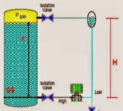
Flow Restriction between the Pressure Vessel System with a Flare System
There is a new pressure vessel to be installed and the existing flare system that has a certain capacity. The capacity of the existing flare system actually has been designed to not take into account the presence of a new pressure vessel, while additional flare to create a new system to increase the capacity of the existing flare system is not economical.
On one hand, the capacity of the flare is certainly not to be missed and one solution is to install RO which has a function as a flow restrictor.
Installation in the downstream RO BDV is generally done on the advice of study over pressure protection and blowdown study, in order to flare its capacity is not exceeded.

Simple sketch pressure vessel, RO, and flare system
Press a different division of the control valve
There is a recycle line of a high-pressure system (discharge of a reciprocating compressor) and into the low-pressure system (separator vessel). It is desirable to regulate the pressure of the fluid that you want to recycle by using a control valve that is not a special design.
The control valve essentially has the function of regulating a fluid flow by creating a pressure difference between upstream and downstream. So the fact that there will be a high enough pressure drop in the control valve.
With such a high-pressure difference between upstream and downstream, the control valve has a load large enough to reduce the fluid pressure. Slightly deviated from the main topic, there are some considerations when designing a control valve that has a high compressive lost:
- At high-pressure drop which means you can develop erosion, abrasion or cavitation on the trim of the control valve.
- In the high-pressure drop hydrate / liquid droplets / solid material makes it possible to form within the valve (depending on the fluid and other materials that shipped).
- The high-pressure drop will cause the outlet temperature of the control valve to be very low (a decrease in pressure is usually followed by a decrease in temperature = Joule-Thomson effect), so in some valve materials can become brittle/brittle which can lead to rupture valve
- High speed due to high-pressure drop that can be eroded downstream piping.
- High-pressure drop which means the amount of energy dissipated in turbulence is quite large and causes noise (noisy).
An alternative application lost control valve for high pressure is to use the special design of the control valve or the division of the difference between the control valve tap with another device, namely the Restriction Orifice.
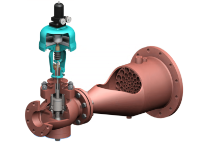
To reduce the load can be mounted Restriction Orifice after the control valve. Installation restriction orifice as shown below.

Simple sketch control valve and pressure vessel
For applications in the downstream RO control valve, basically used the principle / correlation that for a given flow rate and Bore certain size there are differences in pressure (differential pressure) specific.Generally, Differential Pressure needed by those in the control valve between the control valve and Restriction Orifice.
By division Differential Pressure (DP share) the expected effects of the vibrations that would occur in the pipe was not so great due to the change in pressure differential is too great in one device.
It should be noted carefully that the actual control valve is the main tool that bear different press, so that the portion of the largest division of the differential pressure control valve is not in the RO.
DP-sharing applications such as described above can use a special design of a control valve that is capable of working in high pressure differential, of course taking into account that there is a regulated flow of critical line due to the special design of the control valve will certainly have a special fee as well.
If you liked this article, then please subscribe to our YouTube Channel for Instrumentation, Electrical, PLC, and SCADA video tutorials.
You can also follow us on Facebook and Twitter to receive daily updates.
Read Next:
- Flow Standards
- Turbine Flow Meter Verification
- Practical Calibration Standard
- Digital Control Valve Principle
- DP Capillary Seal Level Transmitter


Are there sources for your article?
Especially about the behaviour of pressure through restriction orifice and orifice?
Many thanks in advance, interesting article!
kindly tell me installation parameters of orifrice plate what is the exact point to fix orifice
shall install the restriction orifice ( RO ) in any direction even though it is marked upstream on the tab. Pls.clarify.