Find out the configuration of Lower Range Value (LRV) and Upper Range Value (URV) of a Differential Pressure (DP) Level Transmitter. Every DP transmitter needs to be configured using a HART communicator.
Now let us see the formula for calculating the LRV and URV of the transmitter.
This formula needs two values only
S.G – (Specific gravity which has no unit so no tension of compatible units, if the process has given you density it can easily be converted into SG )
Length – All lengths must be entered in the formula as INCHES only !!
The Formula is Pressure(Head) = Specific Gravity * Height
and TADA !! you have answer in inH2O !!
As we are using S.G which means comparing the density with that of water and the height is in inches. Hence when we multiply the two we get the answer in Inches of water column (no matter what the fluid is answer will be in inH2O ).
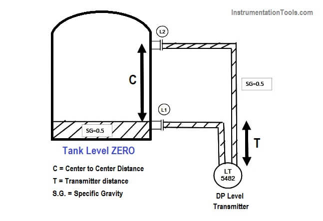
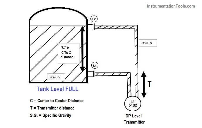
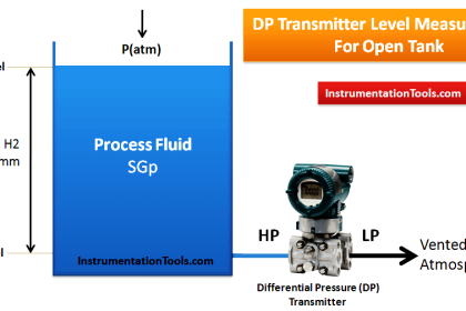
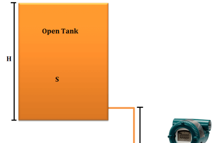
Given:- The C to C Distance is 1000 inches. (center to center)
The Transmitter is 50 inches below lower taping
At 4 mA Condition (LRV)
HP = “ 0.5 * 0 (As at 4 mA no liquid is inside the tank) “ + 0.5 * 50 inches (as transmitter is 50 inches below nozzle)
HP=25 Inches of Water Column is the pressure experienced at HP tap
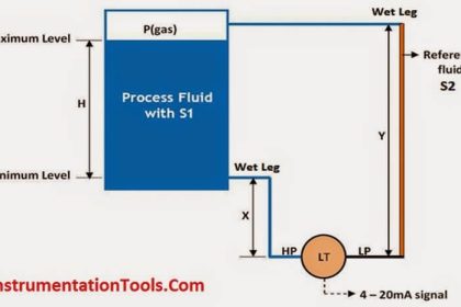
LP = “ 0.5 * 1000 (As the wet leg impulse line is fill with fluid ) “ + 0.5 * 50inches (as transmitter is 50 inches below nozzle)
LP = 500+25=525 Inches of Water Column is the pressure experienced at LP tap
Output =HP-LP= 25-525=-500 inches of water column must be calibrated for 4 mA
Therefore 4mA =(-500) InWC
so, lower range value (LRV) to be configured in Transmitter is -500 InWC
At 20 mA Condition (URV)
HP = 0.5 * 1000 (As at 20 mA liquid will be filled in the entire range) +
0.5 * 50inches (as the transmitter is 50 inches below nozzle)
HP= 500+25=525 Inches of Water Column is the pressure experienced at HP tap
LP = “ 0.5 * 1000 (As the wet leg impulse line is filled with fluid inside the tank ) “ +
0.5 * 50inches (as the transmitter is 50 inches below nozzle)
LP = 500+25=525 Inches of Water Column is the pressure experienced at LP tap
Output = HP-LP=525-525=-0 inches of water column must be calibrated for 20 mA
Therefore 20mA = 0 InWC
so, upper range value (URV) to be configured in the Transmitter is 0 InWC
The calibration Range will be -500 to 0 inches of the water column.
REFERENCE:- This above formula is taken from Emerson and to date I have found this to be the easiest and simplified literature explaining the level calculation.
Author: Asad Shaikh
Profile: Linkedin
Read Also:
- Interface Level Calculation
- Dry Leg & Wet Leg Calculation
- Suppression and Elevation
- Open Tank Level Measurement
- Closed tank Density Measurement
- DP Transmitter Static Pressure Limit
- Level Transmitter Auto Calibration




I consider above mentioned calibration is wrong from my point of view it would be clike this as given below
LRV= 0.5 *50 = 25 INH2O
URV=0.5*1050= 525 INH2O
SPAN=500 INH2O
C’est juste c’est plutôt votre calcul qui est faux. Appliqué la formulation de la pression hydraustatique