In this article, you will learn the daily alarm PLC program using real-time clock instruction as per the required timings using CX programmer Omron PLC.
Real-Time Clock
The Real Time Clock (RTC) in PLC (Programmable Logic Controller) is a hardware component responsible for tracking time in real-time inside the PLC. This Real Time Clock (RTC) allows PLC to perform task scheduling, trigger events at specific times, and record data with a precise time reference.
With RTC, PLC can perform time-based functions, such as time control in the production process, logging data with timestamps, and running operational routines according to a specified schedule.
RTCs in PLCs are usually equipped with backup batteries so that they remain operational even when the PLC is turned OFF or loses power.
Addressing Memory RTC in CX-Programmer
In CX-Programmer, RTC data processing is allocated to Word Memory addresses A351-A354, each Word Memory address contains two RTC time units divided into 8-bits each in the form of BCD (Binary Code Decimal) Data Type and displayed in Hexadecimal units.
RTC can calculate units of time from the scale of Seconds to Years. Data on Word RTC Memory allocation can be processed and moved, and time on PLC can also be set in sync with World real-time or can be set as desired (not synchronized with World real-time).
The table below contains the time distribution for each Word Memory data allocation.
| Word Memory Area | Bit Area | Function | Range Time | Data Type |
| A351 | A351.00 – A351.07 | Seconds | 00 – 59 | BCD |
| A351.08 – A351.15 | Minutes | 00 – 59 | BCD | |
| A352 | A352.00 – A352.07 | Hours | 00 – 23 | BCD |
| A352.08 – A351.15 | Date | 0 – 31 | BCD | |
| A353 | A353.00 – A353.07 | Month | 01 – 12 | BCD |
| A353.08 – A353.15 | Year | 00 – 99 | BCD | |
| A354 | A354.00 – A354.07 | Day of the Week | 00 – 06 | BCD |
| Not used |
Time Comparison Instructions
In CX-Programmer software, the time comparison instruction will compare time data in BCD form with comparison data, when the data comparison condition is “True”, the instruction will be ACTIVE.
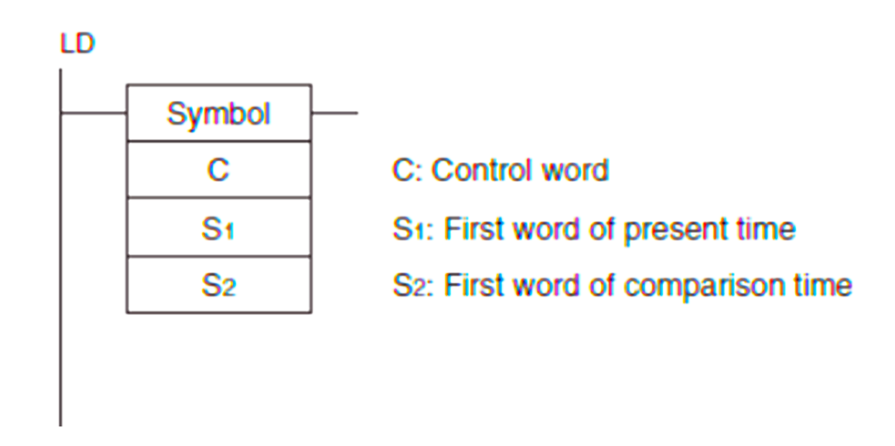
In the Time Comparison instruction above, 3 parameters must be set in the use of Time Comparison instructions.
The time comparison instruction is almost similar to the data comparison instruction, except that there is an addition of the “DT” format.
Following is the Time Comparison Instruction Table
| Result | Flag Status | |||||
| =DT | <>DT | <DT | <=DT | >DT | >=DT | |
| S1 = S2 | ON | OFF | OFF | ON | OFF | ON |
| S1 > S2 | OFF | ON | OFF | OFF | ON | ON |
| S1 < S2 | OFF | ON | ON | ON | OFF | OFF |
Parameter C: Control Word
This C parameter (Control Word) functionally functions to set what units of time will be activated and what units of time are not activated (masked). Time units that are not activated will not be compared with comparison data.
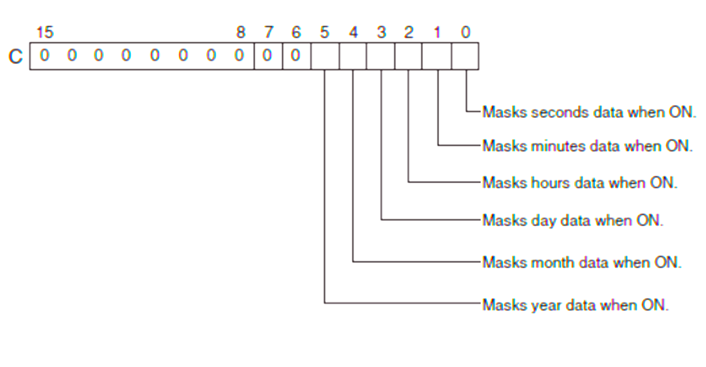
Bits 00 to 05 (starting from the far right) of C determine whether time data will be disabled or not for comparison. If Bits 00 through 05 contain the time units of seconds, minutes, hours, days, months, and years, respectively. If all six values are masked, the instruction will not be executed, the execution condition will be OFF, and the Error Flag will be ENABLED. No time data compared
Covering the unit of time that you do not want to use can be done by activating the Bit, from the normal condition “False/0” to the condition “True/1” and expressing it in Hexadecimal units.
Parameter S1: First Word of Present Time
It is the Word memory address parameter of the RTC, such as A351, A352, A353, and A354.
Parameter S2: First Word of Comparison Time
It is a memory address parameter that is used as comparison data.
Example
When required, the unit of time data format to be compared is Hours, Minutes, and Seconds. Then the units that must be deactivated are Year, Month, and Day.
So the allocation of Memory Bits from Year, Month, and Day should be set to “True/1” while the allocation of Memory Bits from Hours, Minutes, and Seconds should still be set to “False/0”. So the Binary value obtained is “111000” and if converted to Hexadecimal units it becomes “38”.
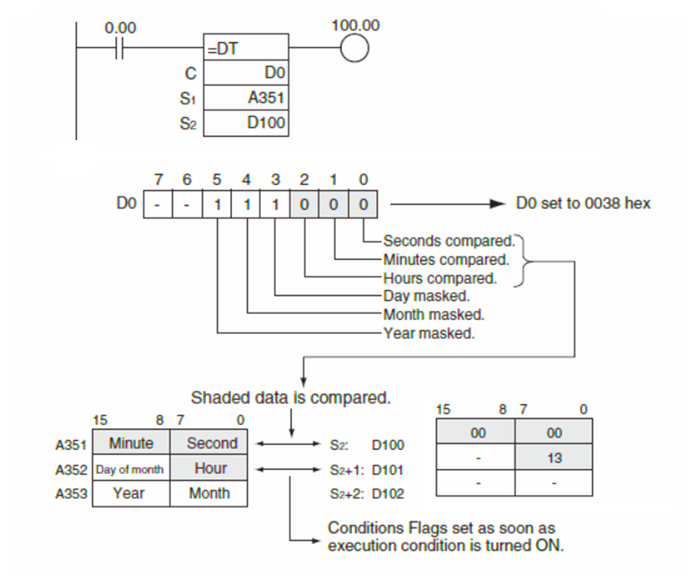
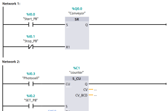
In the picture above, you can see that Word Memory allocation (D100) is used for the comparison of Minutes and Seconds time units from the RTC Memory address (A351), with Bit 00-07 as Seconds data allocation and Bit 08-15 as Minute data allocation. At the Word Memory address (D101) only Bits 00-07 are used because the “Day” data is not enabled.
In the time comparison instruction, 1 Word Memory data allocation is needed for comparison of 2 Time Unit data, because the data type used is BCD which is 8-bit equivalent, so if 2 BCD data becomes 8 + 8 = 16-bit.
Daily Alarm PLC Program
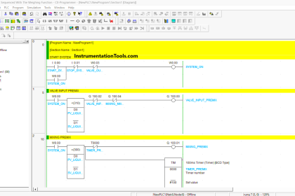
The way the PLC program works above is that when the START contact (0.00) is activated for a moment, the Coil “SYSTEM ON (W0.00)” will be ACTIVE and RUN the program in Rung 1.
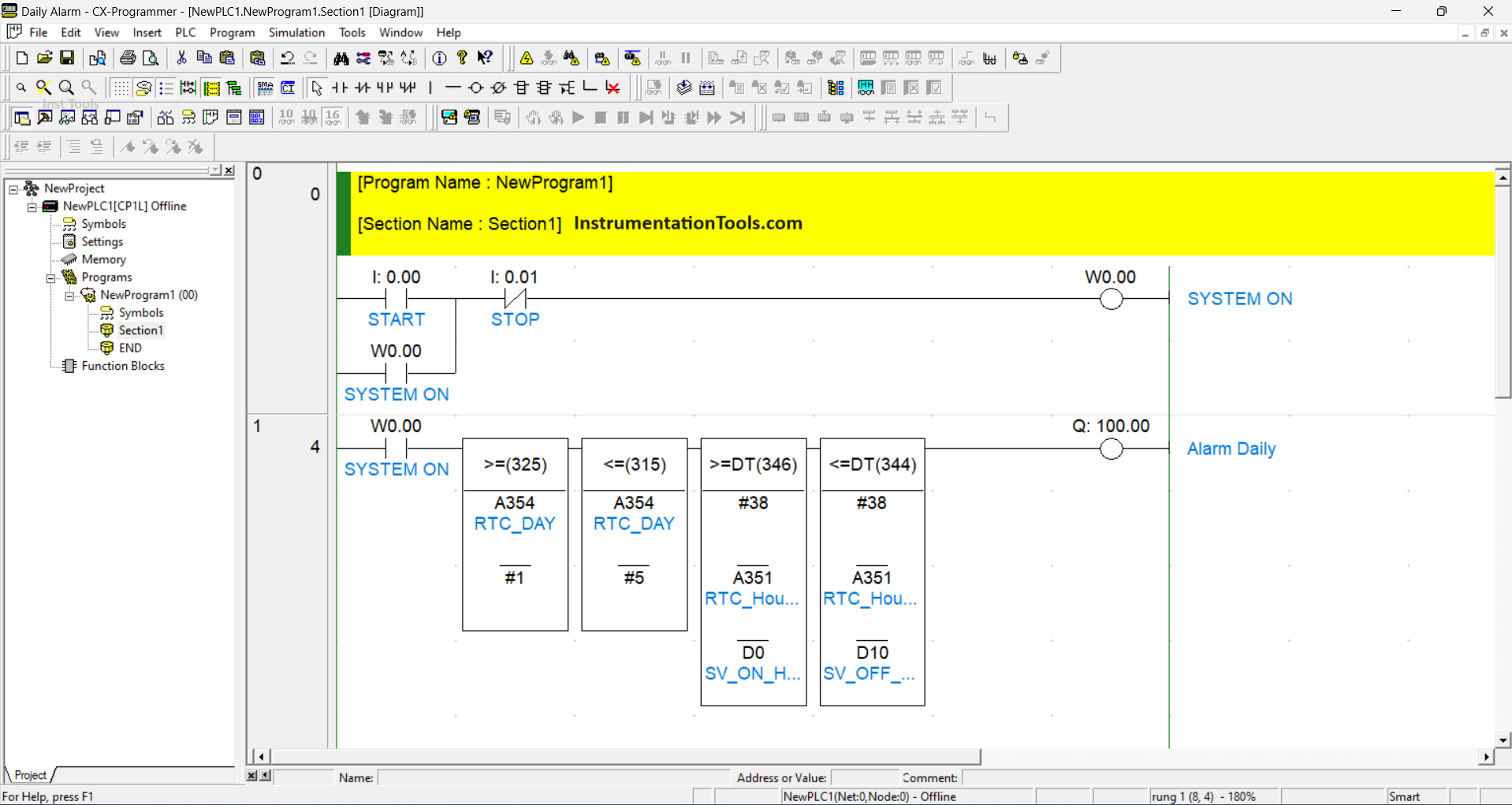
The “>=(325)” instruction will activate when the value of memory address A354 which is the “Day of the Week” data allocation of the RTC is greater than or equal to #1. Value #1 = Monday, meaning the Instruction will ACTIVE on Monday or after Monday.
The “<=(315)” instruction will activate when the value of memory address A354 which is the “Day of the Week” data allocation of the RTC is less than or equal to #5. Value #5 = Saturday, meaning the Instruction will work on Saturday or days before Saturday.
The instruction “>=DT(346)” given by masking #38 indicates that the units of time to be compared are only Hours, Minutes, and Seconds. So if the value of A351 is greater than or equal to the value of the SV_ON comparison data (D0) then the Instruction will be ACTIVE.
The instruction “>=DT(344)” given by masking #38 indicates that the units of time to be compared are only Hours, Minutes, and Seconds. So if the value of A351 is less than or equal to the value of the comparison data SV_OFF (D1) then the Instruction will be ACTIVE and will be OFF if the value of A351 exceeds SV_OFF (D1).
The system will only stop if STOP (0.01) is enabled.
Simulation Results
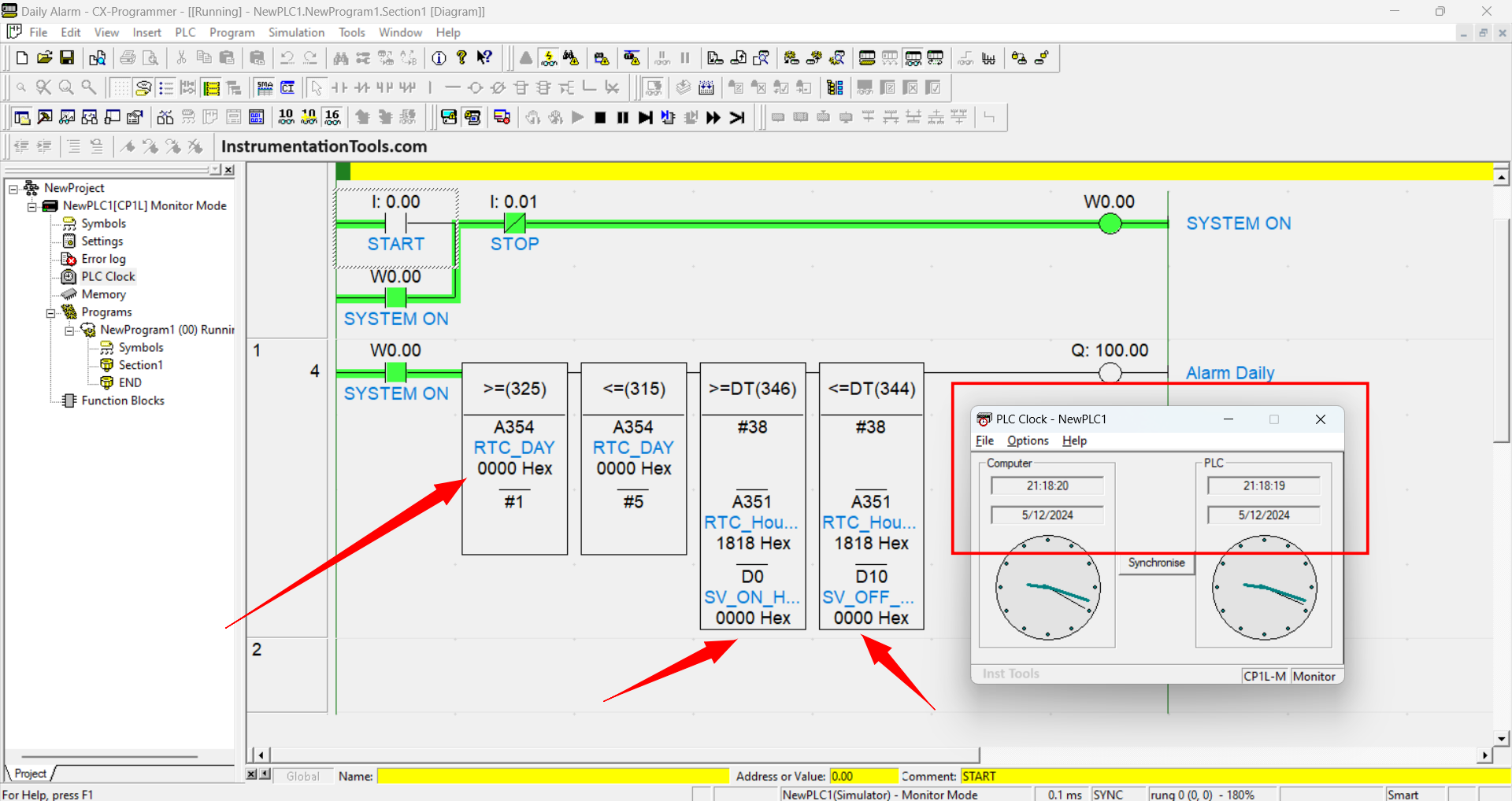
After the Program is run (simulated) the Daily Alarm (100.00) is inactive because the condition of all Instructions is still not set and has not been met.
In Pop-Up, PLC Clock can also be known if the time between PLC and PC / Computer is in Sync.
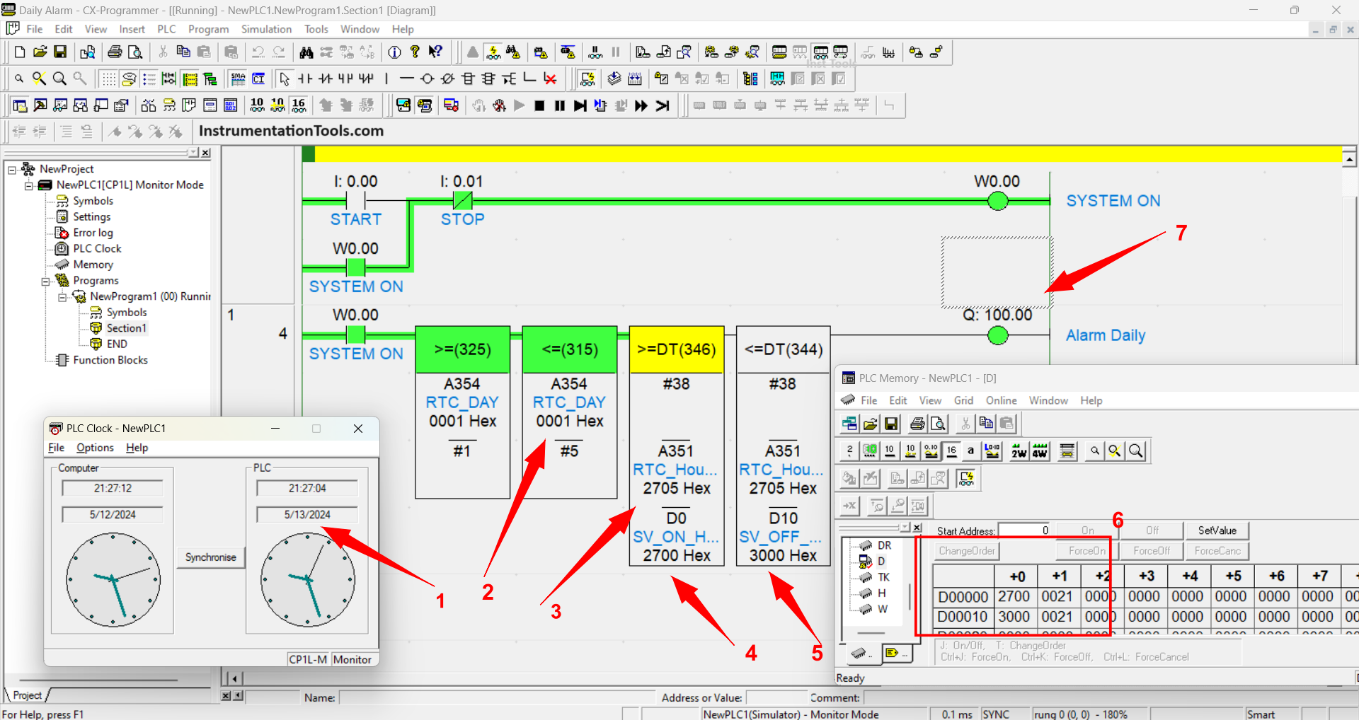
In the picture above, it can be seen that the Daily Alarm Output Coil (100.00) has been activated because all conditions of the Instruction have been met.
PLC Clock is manipulated so that it can be adjusted to the values in the parameters that have been given. Time comparison values can be entered in PLC memory as in Box No. 6.
The SV_ON parameter (D0) is set with a value of “2700” (27 = minutes, 00 = seconds), and a memory allocation (D1) is set with a value of “0021” (00 = Not Used, 21 = Hours).
The SV_OFF parameter (D10) is set with the value “3000” (30 = Minutes, 00 = Seconds) and the memory allocation (D11) is set with the value “0021” (00 = Not used, 21 = Hours).
In conclusion, Daily Alarm is ACTIVE because the day is more than equal to 1 (Monday) and less than equal to 6 (Saturday). Time has also passed 21 Minutes 27 Seconds 00, but less than 21 Minutes 30 Seconds 00 hours.
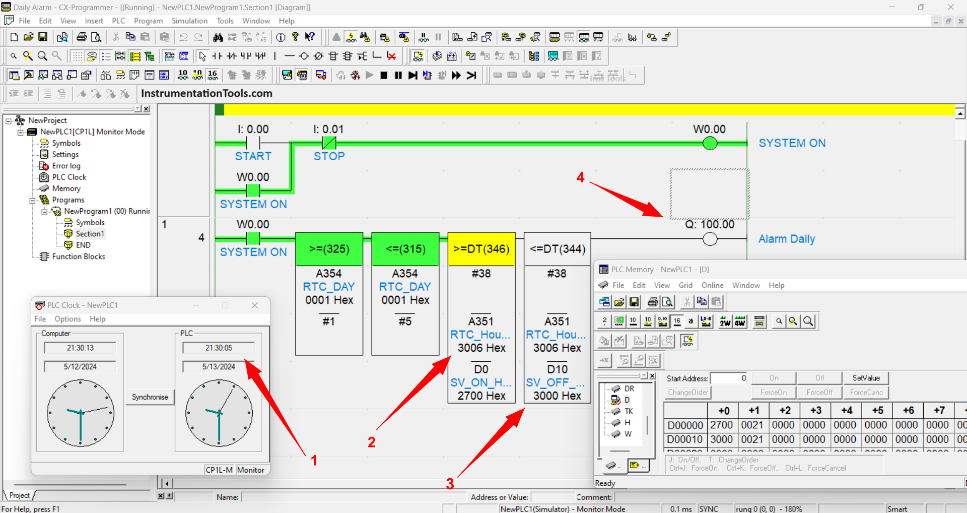
In this phase, the time condition has exceeded the limits of Hours, Minutes, and Seconds so that the Daily Alarm becomes disabled.
If you liked this article, please subscribe to our YouTube Channel for PLC and SCADA video tutorials.
You can also follow us on Facebook and Twitter to receive daily updates.
Read Next:
- PLC and MCC Panel Interface Signals
- VFD Simulator Software Download
- CX-Programmer Products Sorting
- Pneumatic Cylinder & Motor Circuit
- Network Switch in SCADA and DCS