In a FF network segment, the Link Active Scheduler (LAS) device coordinates all communications between segment devices.
Among the many responsibilities the LAS is tasked with are the following:
- Commands non-LAS devices to broadcast data to the segment with “Compel Data” (CD) messages, issued at regular time intervals to specific devices (one at a time)
- Grants permission for non-LAS devices to communicate with “Pass Token” (PT) messages, issued during unscheduled time slots to specific devices (one at a time, in ascending order of address number)
- Keeps all segment devices synchronized with a regular “Time Distribution” (TD) message
- Probes for new devices on the segment with a “Probe Node” (PN) message
- Maintains and publishes a list of all active devices on the network (the Live List)
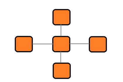
Scheduled Versus Unscheduled Communication
Fieldbus H1 network communication may be divided into two broad categories: scheduled (cyclic) and unscheduled (acyclic). Scheduled communication events are reserved for exchanging critical control data such as process variable measurements, cascaded setpoints, and valve position commands. These scheduled communications happen on a regular, timed schedule so that loop determinism is guaranteed. Unscheduled communications, by contrast, are the way in which all other data is communicated along an H1 segment. Manual setpoint changes, configuration updates, alarms, and other data transfers of lesser importance are exchanged between devices in the times between scheduled communication events.
Both forms of communication are orchestrated by the Link Active Scheduler (LAS) device, of which there is only one active at any given time (Note) on an H1 segment. The LAS issues “token” messages to non-LAS devices commanding (or merely authorizing) them to broadcast to the segment one at a time. Each token message issued by the LAS grants transmission rights to an FF device either for a limited purpose (i.e. the precise message to be transmitted) or for a limited time (i.e. giving that device the freedom to transmit whatever data it desires for a short duration), after which transmission rights return to the LAS. CD tokens are message-specific: each one issued by the LAS commands a single device to immediately respond with a broadcast of some specific data. This is how scheduled (cyclic) communication is managed. PT tokens are time-specific: each one issued by the LAS grants a single device free time to transmit data of lesser importance. This is how unscheduled (acyclic) communication between devices is managed.
Note : In addition to the main LAS, there may be “backup” LAS devices waiting ready to take over in the event the main LAS fails for any reason. These are Link Master devices configured to act as redundant Link Active Schedulers should the need arise. However, at any given time there will be only one LAS. In the event of an LAS device failure, the Link Master device with the lowest-number address will “step up” to become the new LAS.
The LAS also issues a third type of token message: the “Probe Node” (PN) token intended to elicit a response from any new devices connected to the network segment. Probe Node tokens are issued one at a time to each uncommitted device address in search of any new devices.
In addition to transmitting tokens – which by definition are messages granting another device permission to transmit to the network – the LAS also broadcasts other messages necessary for the function of an H1 segment. For example, the “Time Distribution” (TD) message regularly broadcast by the LAS keeps all devices’ internal clocks synchronized, which is important for the coordinated transfer of data.
One of the “internal” tasks of the LAS not requiring network broadcasts is the maintenance of the Live List, which is a list of all known devices functioning on the network segment. New devices responding to “Probe Node” messages will be added to the Live List when detected. Devices failing to return or use PT tokens issued to them are removed from the Live List after a number of attempts. When “backup” LAS devices exist on the segment, the LAS also publishes updated copies of the Live List to them, so they will have the most up-to-date version should the need arise to take over for the original LAS (in the event of an LAS device failure).
In “busy” H1 segments where multiple devices are exchanging data with each other, a heavy traffic load of scheduled communications (CD tokens and their responses) makes it difficult for substantial unscheduled (acyclic) data exchanges to occur. For example, if a device happens to be maintaining a lengthy list of client/server requests in its queue, which it may address only during its allotted acyclic time slots (i.e. when it has been given the PT token from the LAS), it is quite possible the PT token will expire before all the device’s transactions have been completed. This means the device will have to wait for the next acyclic period before it can complete all the unscheduled communication tasks in its queue. The Fieldbus Foundation recommends new H1 segments be configured for no more than 30% scheduled communications during each macrocycle (70% unscheduled time). This should leave plenty of “free time” for all necessary acyclic communications to take place without having to routinely wait multiple macrocycles.
Virtual Communication Relationships (VCR)
A term you will frequently encounter in FF literature is VCR, or “Virtual Communication Relationships.” There are three different types of VCRs in FF, describing three different ways in which data is communicated between FF devices:
- Publisher/Subscriber (scheduled), otherwise known as Buffered Network-scheduled Unidirectional (BNU)
- Client/Server (unscheduled), otherwise known as Queued User-triggered Bidirectional (QUB)
- Source/Sink (unscheduled), otherwise known as Queued User-triggered Unidirectional (QUU)
Publisher/Subscriber: this VCR describes the action of a Compel Data (CD) token. The Link Active Scheduler (LAS) calls upon a specific device on the network to transmit specific data for a timecritical control purpose. When the addressed device responds with its data, multiple devices on the network “subscribing” to this published data receive it simultaneously. This is how process-control variables (PV, PID output, etc.) are communicated between instruments comprising a FF control loop. The publisher/subscriber VCR model is highly deterministic because all such communications occur on a precisely defined schedule.
Client/Server: this VCR describes one class of unscheduled communications, permitted when a device receives a Pass Token (PT) message from the LAS. Each device maintains a queue (list) of data requests issued by other devices (clients), and responds to them in order as soon as it receives the Pass Token. By responding to client requests, the device acts as a server. Likewise, each device can use this time to act as a client, posting their own requests to other devices, which will act as servers when they receive the PT token from the LAS. This is how non-critical messages such as maintenance and device configuration data, operator setpoint changes, alarm acknowledgments, PID tuning values, etc. are exchanged between devices on an H1 segment. Trend data (process variables recorded over time and displayed in time-domain graph form) may also be communicated using this type of VCR, with a “burst” of collected samples communicated per server message. Client/server communications are checked for data corruption by their receivers, to ensure reliable data flow.
Source/Sink (also called Report Distribution): this VCR describes another class of unscheduled communications, permitted when a device receives a Pass Token (PT) message from the LAS. This is where a device broadcasts data out to a “group address” representing many devices. Source/sink communications are not checked for data corruption, as are client/server communications. Examples of messages communicated in a FF segment using the source/sink VCR include trend reports and alarms.
An analogy for making sense of VCRs is to imagine lines drawn between FF devices on a segment to connect their various messages to other devices. Each line represents an individual transmission which must take place some time during the macrocycle. Each line is a VCR, some managed differently than others, some more critical than others, but all of them are simply communication events in time. A specific example of this is in the function block diagrams for a FF control system, where connecting lines between function blocks residing in different devices represent messages sent by the Publisher/Subscriber VCR method. Each line connecting function blocks between different devices is a message in response to a CD (Compel Data) token issued by the LAS, ensuring the deterministic transfer of critical control data between function blocks necessary for the control system to reliably function.
The Source/Sink VCR is the preferred method for communicating trend data, but trends may be communicated via any of the three VCR types. All other factors being equal, acyclic communication (either Source/Sink or Client/Server) of trend data occupies less network bandwidth than cyclic communication (Publisher/Subscriber).
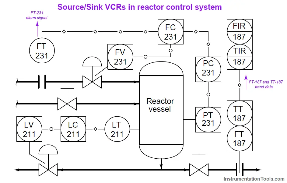
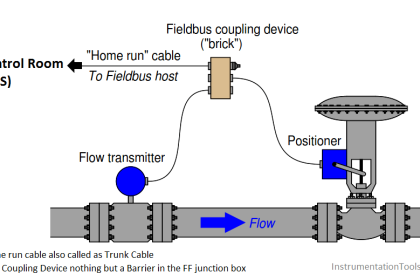
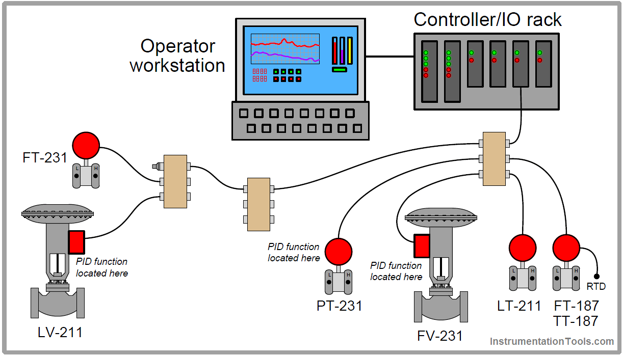
For example, consider this H1 segment connected to an interface card on a DCS rack, followed by a P&ID showing the relationships between the instruments:
Loop 211 is a simple PID level control, regulating liquid level in the reactor vessel by releasing liquid from the bottom. Loop 187 is a simple indicating/recording system for temperature and flow, the signals coming from a multivariable transmitter. Loop 231 is a cascaded pressure/flow control system, with reactor pressure as the master variable and feed flow as the slave variable: the pressure controller (residing inside pressure transmitter PT-231) provides remote setpoint values to the flow controller (residing in the flow control valve FV-231), which then adjusts the position of the valve to achieve the desired feed flow rate into the reactor until reactor pressure stabilizes at setpoint.
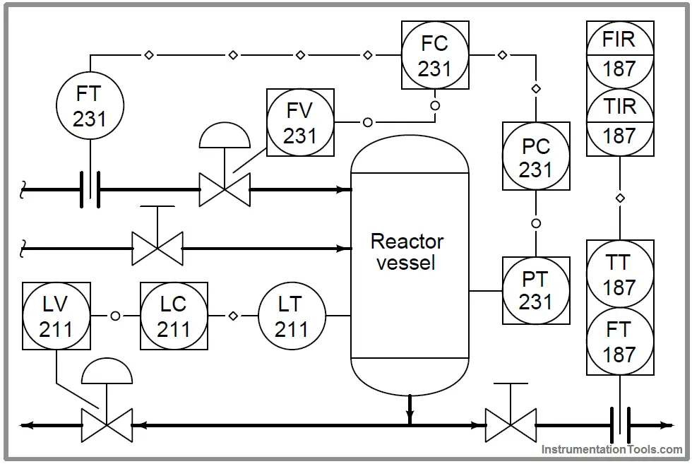
Note the different line types used to represent digital signals in the P&ID: lines with diamond symbols represent data sent over Fieldbus cable, while lines with hollow circles represent data sent between functions within the same physical device. These latter “internal” data links help the reader discern which functions reside in which physical instruments. Functions residing within the same FF device must also share the same loop number. These standards for P&ID notation come from the Fieldbus Foundation’s System Engineering Guidelines document and from the ANSI/ISA-5.1-2009 “Instrumentation Symbols and Identification” standard.
For example, the PID control function represented by FC-231 resides within the valve positioner (FV-231), because those two bubbles share the same loop number and are connected with lines having hollow circles (which means they are parts of one homogeneous system rather than independent instruments). Likewise, the same line symbology tells us that pressure control PID function PC-231 resides within the pressure transmitter PT-231.
Control-critical variables communicated over the segment between devices include (Note) the output value of PC-231 (FC-231’s remote setpoint value), flow transmitter FT-231’s process variable measurement, and the process variable from level transmitter LT-211. These are all Publisher/Subscriber VCRs, transmitted at the request of a Compel Data (CD) token issued by the LAS device on a tightly controlled schedule:
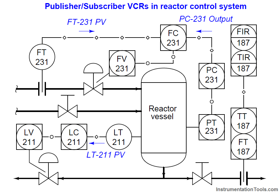
Note : One other variable communicated in Publisher/Subscriber mode is the “back calculation” signal sent from slave (flow) controller FC-231 to master (pressure) controller PC-231. This particular signal is beyond the immediate scope of the discussion, and therefore is mentioned here only as a footnote.
Messages such as operator-adjusted setpoint values and maintenance tasks occur as Client/Server VCRs, done during the “unscheduled” communication times in the LAS’s sequence. The LAS device issues Pass Token (PT) messages to each device, giving permission for each device (one at a time) to transmit such information as necessary. Examples of such non-critical messages in our reactor control system are shown here:
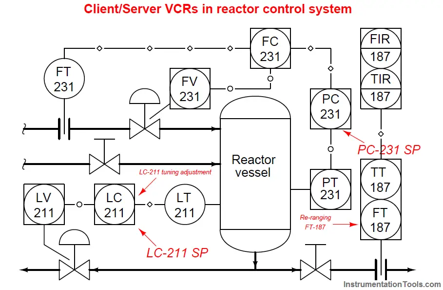
Finally, our third VCR (Source/Sink) finds application in the reactor control system for flow transmitter FT-187, broadcasting its flow trend data during “unscheduled” periods in the LAS’s cycle, as well as for instrument alarm messages. Like the Client/Server messages, this one is prompted when the device receives a special Pass Token (PT) signal from the LAS, giving temporary permission for that device to broadcast its data: