Inst ToolsInst ToolsInst Tools
  • Courses
  • Automation
    • PLC
    • Control System
    • Safety System
    • Communication
    • Fire & Gas System
  • Instrumentation
    • Design
    • Pressure
    • Temperature
    • Flow
    • Level
    • Vibration
    • Analyzer
    • Control Valve
    • Switch
    • Calibration
    • Erection & Commissioning
  • Interview
    • Instrumentation
    • Electrical
    • Electronics
    • Practical
  • Q&A
    • Instrumentation
    • Control System
    • Electrical
    • Electronics
    • Analog Electronics
    • Digital Electronics
    • Power Electronics
    • Microprocessor
  • Request
Search
  • Books
  • Software
  • Projects
  • Process
  • Tools
  • Basics
  • Formula
  • Power Plant
  • Root Cause Analysis
  • Electrical Basics
  • Animation
  • Standards
  • 4-20 mA Course
  • Siemens PLC Course
Reading: Cut-outs between Platforms or Grating for Field Instruments
Share
Font ResizerAa
Inst ToolsInst Tools
Font ResizerAa
  • Courses
  • Design
  • PLC
  • Interview
  • Control System
Search
  • Courses
  • Automation
    • PLC
    • Control System
    • Safety System
    • Communication
    • Fire & Gas System
  • Instrumentation
    • Design
    • Pressure
    • Temperature
    • Flow
    • Level
    • Vibration
    • Analyzer
    • Control Valve
    • Switch
    • Calibration
    • Erection & Commissioning
  • Interview
    • Instrumentation
    • Electrical
    • Electronics
    • Practical
  • Q&A
    • Instrumentation
    • Control System
    • Electrical
    • Electronics
    • Analog Electronics
    • Digital Electronics
    • Power Electronics
    • Microprocessor
  • Request
Follow US
All rights reserved. Reproduction in whole or in part without written permission is prohibited.
Inst Tools > Blog > Erection & Commissioning > Cut-outs between Platforms or Grating for Field Instruments

Cut-outs between Platforms or Grating for Field Instruments

Last updated: February 27, 2020 5:01 pm
Editorial Staff
Erection & Commissioning Instrumentation Design
No Comments
Share
2 Min Read
SHARE

Usually, Cut-outs between platforms or grating are not given due importance as they can be done on-site.

While we have such an approach, there is a concern that could go unnoticed.

This concern is regarding corrosion.

Let’s understand this by taking a practical example.

Platform or Grating for Field Instruments

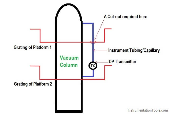
Below is a Diagram of a Vacuum column with 2 platforms/ gratings.

Cut-outs between Platforms or Grating for Field Instruments

And we have placed a DP transmitter on platform/grating number 2, but HP tapping of transmitter is on grating/platform 1.

And we require cut-out for the same.

Usually, for corrosive environment, the materials that are specified are “Hot dip galvanized”.

So when you have fixed all the gratings etc on the tower and then decide to drill the cut-out then the edges get exposed.

These cannot be hot dip galvanized at this stage hence they are just painted.

Paint is temporary solution as compared to Hot dip galvanization.

Hence when the paint gets peeled of gradually along the edges, it would get corroded and would eventually turn into a safety hazard.

So in conclusion cut out of grating left to site personnel will have its edges painted which is not at par with being “hot dip galvanized” hence corrosion can gradually creep into it.

These corroded edges could cause injury to the site personal.

Hence prefer giving cut out during the manufacturing of this gratings so that the edges are also hot dip galvanized.

Thanks for reading.

Author: Asad Shaikh

Read Next:

  • Instrument Wrong Practice
  • Good and Bad Wiring
  • Positive Material Identification
  • How to Install Thermowell?
  • Instrument Hook Up Drawings
Don't Miss Our Updates
Be the first to get exclusive content straight to your email.
We promise not to spam you. You can unsubscribe at any time.
Invalid email address
You've successfully subscribed !

Continue Reading

Why we use Cable Shielding with Ferrites ?
Instrumentation Engineer in Process Plant Project
Instrumentation and Electrical Teams Interactions (Detail Design Engineering)
What is Double Block and Bleed Valves?
Temperature Gauges and Elements : Detailed Specifications
When to use a Diaphragm Seal?
Share This Article
Facebook Whatsapp Whatsapp LinkedIn Copy Link
Share
Leave a Comment

Leave a Reply Cancel reply

Your email address will not be published. Required fields are marked *

Stay Connected

128.3kFollowersLike
69.1kFollowersFollow
210kSubscribersSubscribe
38kFollowersFollow

Categories

Explore More

Competency Factors of Instrument & Control Engineer (Design Engineering)
Field Instruments Selection Aid
Process Design of Instrument Air System
Single and Three Phase Immersion Electrical Heaters Wiring Circuits
Solenoid Valve Selection Criteria
4-20 mA Loop Splitter
Control Valves Pre-Commissioning Checklist
What is Material Take Off (MTO)? – Purpose, Components, Uses

Keep Learning

Monsoon Protection for Field Instruments and Junction Boxes

Monsoon Protection for Field Instruments and Junction Boxes

magnetic-flow-meter-earthing

Importance of Magnetic Flow Meters Grounding

Switch Contact checking with oscilloscope

What is Contact bounce ?

Instrument Air Compressor Control Philosophy

Instrument Air Compressor Control Philosophy

Instrument Datasheet

What is Instrument DataSheet ?

O Ring Failure

How O-Ring Failure caused NASA’s shuttle to Blast ?

Wrong Orifice Installation

How Not to Install an Instrument and Wrong Practices

Kv-value of a valve is determined by a standardised test

Calculate Flow Coefficient Kv of Solenoid Valve

Learn More

Interview Questions and Answers on Load Cell

Auto Cane Feed Control System using DCS

Auto Cane Feed Control System using DCS – Sugar Factory

Reliability of a Control System

Reliability of a Control System

PLC Program for Tank Heating Control using Heater

PLC Programming for Tank Heating Control using Heater

Firmware Version in Siemens PLC

What is the Firmware Version of a PLC? – Siemens PLC Hardware

Loss in Weight Liquid PLC System

Dosing Pump PLC Logic

6 Pieces of Essential Equipment For PCB Assembly

6 Pieces of Essential Equipment For PCB Assembly

Ladder Diagram Example using Memory Bits and Set Coils

Ladder Diagram Example using Memory Bits and Set Coils

Menu

  • About
  • Privacy Policy
  • Copyright

Quick Links

  • Learn PLC
  • Helping Hand
  • Part Time Job

YouTube Subscribe

Follow US
All rights reserved. Reproduction in whole or in part without written permission is prohibited.
Welcome Back!

Sign in to your account

Username or Email Address
Password

Lost your password?