Inst ToolsInst ToolsInst Tools
  • Courses
  • Automation
    • PLC
    • Control System
    • Safety System
    • Communication
    • Fire & Gas System
  • Instrumentation
    • Design
    • Pressure
    • Temperature
    • Flow
    • Level
    • Vibration
    • Analyzer
    • Control Valve
    • Switch
    • Calibration
    • Erection & Commissioning
  • Interview
    • Instrumentation
    • Electrical
    • Electronics
    • Practical
  • Q&A
    • Instrumentation
    • Control System
    • Electrical
    • Electronics
    • Analog Electronics
    • Digital Electronics
    • Power Electronics
    • Microprocessor
  • Request
Search
  • Books
  • Software
  • Projects
  • Process
  • Tools
  • Basics
  • Formula
  • Power Plant
  • Root Cause Analysis
  • Electrical Basics
  • Animation
  • Standards
  • 4-20 mA Course
  • Siemens PLC Course
Reading: Control Valve Flow Direction
Share
Font ResizerAa
Inst ToolsInst Tools
Font ResizerAa
  • Courses
  • Design
  • PLC
  • Interview
  • Control System
Search
  • Courses
  • Automation
    • PLC
    • Control System
    • Safety System
    • Communication
    • Fire & Gas System
  • Instrumentation
    • Design
    • Pressure
    • Temperature
    • Flow
    • Level
    • Vibration
    • Analyzer
    • Control Valve
    • Switch
    • Calibration
    • Erection & Commissioning
  • Interview
    • Instrumentation
    • Electrical
    • Electronics
    • Practical
  • Q&A
    • Instrumentation
    • Control System
    • Electrical
    • Electronics
    • Analog Electronics
    • Digital Electronics
    • Power Electronics
    • Microprocessor
  • Request
Follow US
All rights reserved. Reproduction in whole or in part without written permission is prohibited.
Inst Tools > Blog > Control Valves > Control Valve Flow Direction

Control Valve Flow Direction

Control Valve Flow Direction has a relationship with a failure action, High Delta Pressure, Cavitation, and percentage opening of valve.

Last updated: September 28, 2022 2:38 pm
R Jagan Mohan Rao
Control Valves
3 Comments
Share
4 Min Read
SHARE

The control valves flow direction based on different factors like delta pressure, cavitation, failure action, and percentage of control valve opening.

Contents
Control Valve Flow DirectionFlow to Close (FTC)Flow to Open (FTO)

Control Valve Flow Direction

Control Valves Flow Direction

Types of control valve flow direction

  1. Flow to Open (FTO)
  2. Flow to Close (FTC)

Flow to Close (FTC)

When the fluid passes on top of the plug, it gives a closing action to the plug. This is called the flow to close (FTC) type flow direction. The effects of cavitation are less and it requires more breakaway torque to open and less torque for closing the valve. This is mainly used for low-pressure applications.

Flow to close FTC) is used in anti-cavitation trim with rotary valves are the special applications.
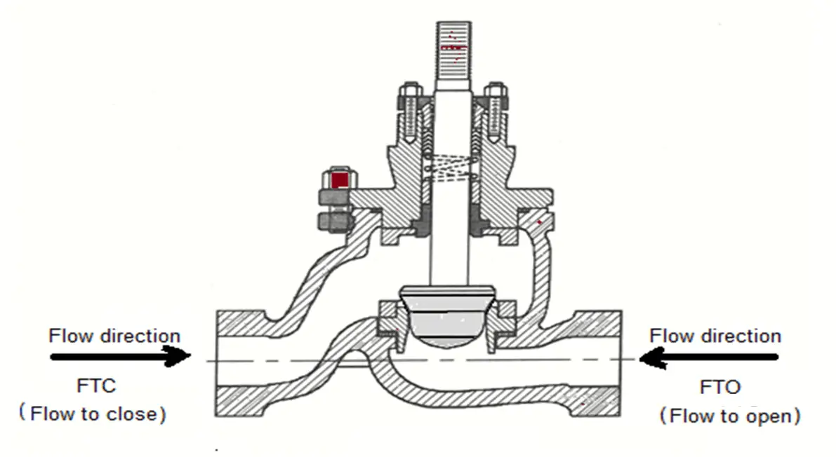
Types of valve flow direction

Flow to Open (FTO)

When the fluid flows pass through and faces the plug directly, it gives an opening act to the plug. This is called a flow-to-open (FTO) type of flow direction.

As the flow is upward direction on the plug, it requires higher closing torque and less opening torque and is mainly used for high-pressure applications.

Unless there is a special reason almost all general service applications are Flow to open (FTO).

Flow Direction of Ball Valve

The flow direction of ball valves is bidirectional irrespective of design such as floating ball or trunnion mounted. On the upstream or downstream, two identical round seats are fixed and the ball will move on it.
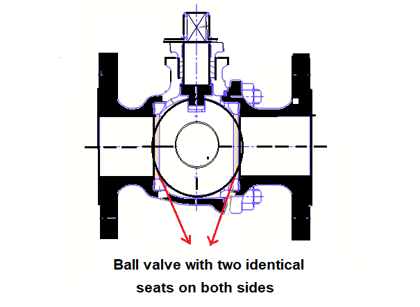
Flow direction of Ball valve

Image Courtesy: Neles

Changing the direction of the ball valve during installation does not affect the sealing performance.

Unidirectional Ball Valve

There are certain ball valves that are marked flow direction need to pay attention to them while installation.

For example, the C type ball valve is mounted on a single seat is meant for the unidirectional flow control valve.
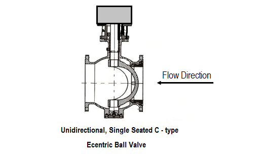
Unidirectional Ball Valve Flow Direction

Image Courtesy: Metso

Also called half ball valve or eccentric ball valve.

In certain working conditions, the double-seated ball valves are designed in a single flow direction. In the upstream side of the ball, a hole is drilled for the pressure relief side. This is found in liquid chlorine, LNG applications.
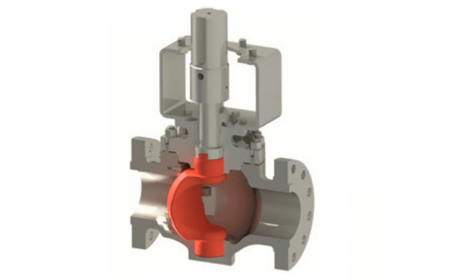
Ball valve Directional

Image Courtesy: Emerson

Single seated ball valves V port ball valves, single-seat shall be connected to the upstream side of the valve.

Flow Direction of Globe Valve

The globe valve is mostly used for throttling flow control. Shut off is accomplished by moving the disc against the flow stream. The flow pattern across globe valve changes in direction, resulting in greater resistance to flow results in high-pressure drop.

The globe valve must be mounted in proper relation to the media flow as indicated by the flow direction marked on the valve body.

This valve is considered unidirectional and must be installed on the pressure side.

For high-temperature steam service applications, globe valves installed so that pressure is above the disc.

For temperature application, the globe valves installed so that pressure is below the disc. This promotes smooth operation, helps protect the packing, and helps the certain amount of erosion action on the seat and disc surfaces.

Flow Direction of Butterfly Valve

Butterfly valves are bidirectional but do not have a preferred flow direction. However, it is strongly suggested to install in the preferred flow direction, as it will extend the valve’s lifespan and will also lower the operating torque.
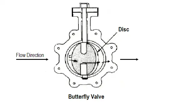
Flow Direction of Butterfly Valve

Image Courtesy: Metso

Read Next

  • Control Valves MCQ
  • Final Control Elements
  • What is Globe Valve ?
  • Solenoid Valves Selection
  • Fundamentals of Valves
Don't Miss Our Updates
Be the first to get exclusive content straight to your email.
We promise not to spam you. You can unsubscribe at any time.
Invalid email address
You've successfully subscribed !

Continue Reading

Types of Failures in Control Valves
Control Valve Cavitation and Flashing
Control Valve Performance with Constant Pressure
Metal Seated Valves and Soft Seated Valves : Differences
Valve Materials Comparison Notes
Current to Pressure (I/P) Converter Principle
Share This Article
Facebook Whatsapp Whatsapp LinkedIn Copy Link
Share
3 Comments
  • Bandar Alotaibi says:
    November 15, 2020 at 12:04 am

    The Flow to Close (FTC) & Flow to Open (FTO) explanation at the beginning is reversed or opposite

    Reply
  • Mike Dennison says:
    May 25, 2021 at 11:36 pm

    Are the flow directions backwards in the image between Flow to Close and Flow to Open sections?

    Reply
    • Kamran says:
      July 16, 2023 at 4:04 pm

      No
      It is towards the front

      Reply

Leave a Reply Cancel reply

Your email address will not be published. Required fields are marked *

Stay Connected

128.3kFollowersLike
69.1kFollowersFollow
210kSubscribersSubscribe
38kFollowersFollow

Categories

Explore More

Solenoid Valve Functional Testing
What is Stop Check valve ?
Pressure Relief Valve Terminology
Top 80+ Valve Questions and Answers
What is Directional Control Valve (DCV)?
Self Actuated Pressure Control Valve Functional Testing
What is a Boiler Pressure Relief Valve?
Shaft and Coupling Bore Tapers Repair Caused Frequent Shutdowns

Keep Learning

Deluge Valve Operation using Solenoid Valve Animation

Deluge Valve Operation

Valves MCQ

Valves MCQ

SMART Control Valve Positioner

Electronic Valve positioners

Functional Testing of Control Valve Positioners

Functional Testing of Control Valve Positioners

Difference between Butterfly Valves and Ball Valves

Difference between Butterfly Valves and Ball Valves

Solenoid Valve Terminology

Solenoid Valves Terminology

Online Testing of Solenoid Valve

Design and Accessories Required for Online Testing of Solenoid Valve

control-valves-classification

Types of Control Valves

Learn More

Address Overlapping in Tia Portal

How to Check Address Overlapping in Tia Portal?

Types of MCB

Types of MCB

Thermocouples

Important Factors for Thermocouple Selection

Instrumentation Commissioning

Commissioning Documents for Instrumentation Engineers

Flow Meter Questions and Answers

Flow Meter Questions and Answers

Hydraulic Actuator Principle

What is a Hydraulic Actuator ?

Useful Trigonometry Website for Students Math Help

The Impact of Knowledge Management Platforms on Business Operations

Identify Instruments in Piping and instrumentation Diagram

Identify Instruments in Piping and instrumentation Diagram

Menu

  • About
  • Privacy Policy
  • Copyright

Quick Links

  • Learn PLC
  • Helping Hand
  • Part Time Job

YouTube Subscribe

Follow US
All rights reserved. Reproduction in whole or in part without written permission is prohibited.
Welcome Back!

Sign in to your account

Username or Email Address
Password

Lost your password?