Inst ToolsInst ToolsInst Tools
  • Courses
  • Automation
    • PLC
    • Control System
    • Safety System
    • Communication
    • Fire & Gas System
  • Instrumentation
    • Design
    • Pressure
    • Temperature
    • Flow
    • Level
    • Vibration
    • Analyzer
    • Control Valve
    • Switch
    • Calibration
    • Erection & Commissioning
  • Interview
    • Instrumentation
    • Electrical
    • Electronics
    • Practical
  • Q&A
    • Instrumentation
    • Control System
    • Electrical
    • Electronics
    • Analog Electronics
    • Digital Electronics
    • Power Electronics
    • Microprocessor
  • Request
Search
  • Books
  • Software
  • Projects
  • Process
  • Tools
  • Basics
  • Formula
  • Power Plant
  • Root Cause Analysis
  • Electrical Basics
  • Animation
  • Standards
  • 4-20 mA Course
  • Siemens PLC Course
Reading: Control Valve Volume Booster Working Principle
Share
Font ResizerAa
Inst ToolsInst Tools
Font ResizerAa
  • Courses
  • Design
  • PLC
  • Interview
  • Control System
Search
  • Courses
  • Automation
    • PLC
    • Control System
    • Safety System
    • Communication
    • Fire & Gas System
  • Instrumentation
    • Design
    • Pressure
    • Temperature
    • Flow
    • Level
    • Vibration
    • Analyzer
    • Control Valve
    • Switch
    • Calibration
    • Erection & Commissioning
  • Interview
    • Instrumentation
    • Electrical
    • Electronics
    • Practical
  • Q&A
    • Instrumentation
    • Control System
    • Electrical
    • Electronics
    • Analog Electronics
    • Digital Electronics
    • Power Electronics
    • Microprocessor
  • Request
Follow US
All rights reserved. Reproduction in whole or in part without written permission is prohibited.
Inst Tools > Blog > Control Valves > Control Valve Volume Booster Working Principle

Control Valve Volume Booster Working Principle

Last updated: August 30, 2019 5:17 pm
Editorial Staff
Control Valves
1 Comment
Share
6 Min Read
SHARE

A pneumatic air volume booster reproduce a low flow control signal with a higher regulated flow output pressure. It uses an unregulated input pressure to maintain a regulated output pressure under flowing and non-flowing conditions.

Contents
Volume BoosterPrinciple of OperationAdvantages :

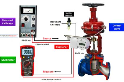
The volume booster is connected to the supply line and the output plumbing. It receives a pneumatic control signal, however, from another device, such as a transducer, valve positioner or other control means.

This pneumatic signal controls the pressure into and out of the booster, while allowing the booster to flow the maximum volume of the supply line. Boosters may also be referred to as pilot-operated regulators, as your control or pilot signal maintains the pressure control.

The regulated output of a pneumatic air volume booster can be any of the following:
      • A direct reproduction of the pneumatic control signal
      • A multiple of the pneumatic control signal
      • A fraction of the pneumatic control signal

The volume booster ratio is the multiplier or divider of signal pressure to output pressure. For example, a 2:1 ratio means output pressure is 1/2 the signal pressure. Similarly, a 2:1 ratio would provide output pressure twice the signal pressure. Note, however, the output pressure can never exceed the supply pressure to the booster.

Often the signal pressure is lower than the supply pressure because a control device (valve positioner, I/P, etc.) will only handle a lower supply pressure.

The volume booster is used to improve stroking speed. If precision valve control is required, the use of a positioner is recommended. If the volume booster is to be used for on/off control, the integral bypass restriction on the booster must be closed.

Volume Booster

A volume booster is used in a pneumatic control system to relay a low flow signal as one with greater flow volume. The common configuration is to provide a 1:1 ratio between the input and output pressure, keeping the input and output signals the same pressure. Products are available that deliver different ratios.

The general purpose of a volume booster is to provide a relay between a system with low flow volume and one with higher volume requirements.

A typical example is a pneumatic actuator. The flow available through the pneumatic signal line may be insufficient to deliver the response rate desired from the pneumatic actuator.

A volume booster, with control over an independent air supply, solves this challenge with increased flow volume at the same pressure as the control signal.

Volume boosters are simple in operation. The input signal applies force to one side of a diaphragm, the output pressure to the other.

An imbalance between the two applied pressures will cause the diaphragm to move, changing the position of the valve and the outlet pressure until the two forces are again in balance.

Little maintenance is required when the units are properly installed and supply air is of good quality.

Figure 1. Sectional View of Volume Booster

Valve Volume Booster Parts

Image Courtesy : Emerson

Principle of Operation

Refer to figures 1 and 2. Because of the bypass restriction, large input signal changes register on the booster input diaphragm sooner than in the actuator.

A large, sudden change in input signal causes a pressure differential to exist between the input signal and the output of the booster.

When this occurs, the diaphragms move to open either the supply port or the exhaust port, whichever action is required to reduce the differential.

The port remains open until the difference between the booster input and output pressures returns to within the deadband limit of the booster.

With the bypass restriction adjusted for stable operation, a signal with small magnitude and rate changes passes through the bypass restriction and into the actuator without initiating booster operation.

Both supply and exhaust ports remain closed, preventing unnecessary air consumption and possible saturation of positioner relays.

Volume Booster Working Principle

Image Courtesy : Emerson

Advantages :

  • Quick response with increeased actuator stroking speeds
  • Maintains correct actuator postioning at high stroking speeds
  • Adjustable by pass valve provides good operational sensitivity
  • High stability which allow normal slow actuator response to slow signal changes
  • Capable of using high pressure plant air supply
  • Different Booster sizes available to suit wide range of actuator sizes
  • Main internal air supply valve with Soft seat insert for tight shut off

Source : Emerson & msjacobs

Articles You May Like :

Control Valve Failure Mode

I/P Converter Calibration

What is Plug Valve ?

Types of Control Valves

ESDV : How it Works ?

Don't Miss Our Updates
Be the first to get exclusive content straight to your email.
We promise not to spam you. You can unsubscribe at any time.
Invalid email address
You've successfully subscribed !

Continue Reading

Basic Parts of Control Valves
Control Valve Performance with Constant Pressure
Self Actuated Pressure Control Valve Functional Testing
How Needle Valve Works ?
Basics of Butterfly Valves
Working Principle of Hydraulic Actuators
Share This Article
Facebook Whatsapp Whatsapp LinkedIn Copy Link
Share
1 Comment
  • Louis Reeves says:
    January 15, 2017 at 4:33 pm

    As a general rule, large volume actuators will need volume boosters when stroking time is critical. However, this does affect the gain of the positioners somewhat, and particularly Digital positioners, so care must be taken when controller tuning is done on these valves as boosters will introduce some lag in the response to control in small signal steps.

    Reply

Leave a Reply Cancel reply

Your email address will not be published. Required fields are marked *

Stay Connected

128.3kFollowersLike
69.1kFollowersFollow
210kSubscribersSubscribe
38kFollowersFollow

Categories

Explore More

Pressure Relief Valve Terminology
Basics of Control Valves
What is Mixing or Diverting Valve ?
Pilot-operated Relief Valve Principle
Directional Control Valves Working Principle
Bellows Seal Valve Working Principle
Valve Actuator Bench Set
Face to Face Dimension of Control Valve

Keep Learning

Control valve sizing

Basics of Control Valve Sizing

Control Valve Parts

Control Valve Parts Questions and Answers

Butterfly check valves

What is Butterfly Check Valve ?

Diaphragm Valves

How Diaphragm Valves Work ?

Globe Valve Parts

What is Globe Valve ?

Objective Questions on Valves

Objective Questions on Valves

Motor Operated Valve Problems and Troubleshooting

Motor Operated Valve Problems and Troubleshooting

Tie rods double acting cylinder

What is a Pneumatic Cylinder?

Learn More

PLC Sequence Programming Ladder Logic

PLC Sequence Programming Ladder Logic

Modbus Function code 02 – Read Contact(s)

Modbus Function Command Formats

Level Gauge Interface Measurement

Level Gauge Interface & Temperature Problems

Loop Diagram

Documentation and Change Control of PLC or DCS Systems

Calculate Power in Series RC Circuit

Calculate Power in Series RC Circuit

Breather Valve Working Principle

Breather Valve Working Principle

OMRON PLC program for waste-burning automation

Waste-Burning System OMRON PLC Program Example

Electronic Devices & Circuits Objective Questions

Electronic Devices & Circuits Quiz – Set 4

Menu

  • About
  • Privacy Policy
  • Copyright

Quick Links

  • Learn PLC
  • Helping Hand
  • Part Time Job

YouTube Subscribe

Follow US
All rights reserved. Reproduction in whole or in part without written permission is prohibited.
Welcome Back!

Sign in to your account

Username or Email Address
Password

Lost your password?