Inst ToolsInst ToolsInst Tools
  • Courses
  • Automation
    • PLC
    • Control System
    • Safety System
    • Communication
    • Fire & Gas System
  • Instrumentation
    • Design
    • Pressure
    • Temperature
    • Flow
    • Level
    • Vibration
    • Analyzer
    • Control Valve
    • Switch
    • Calibration
    • Erection & Commissioning
  • Interview
    • Instrumentation
    • Electrical
    • Electronics
    • Practical
  • Q&A
    • Instrumentation
    • Control System
    • Electrical
    • Electronics
    • Analog Electronics
    • Digital Electronics
    • Power Electronics
    • Microprocessor
  • Request
Search
  • Books
  • Software
  • Projects
  • Process
  • Tools
  • Basics
  • Formula
  • Power Plant
  • Root Cause Analysis
  • Electrical Basics
  • Animation
  • Standards
  • 4-20 mA Course
  • Siemens PLC Course
Reading: Control Valve Air Lock Relay Working Principle
Share
Font ResizerAa
Inst ToolsInst Tools
Font ResizerAa
  • Courses
  • Design
  • PLC
  • Interview
  • Control System
Search
  • Courses
  • Automation
    • PLC
    • Control System
    • Safety System
    • Communication
    • Fire & Gas System
  • Instrumentation
    • Design
    • Pressure
    • Temperature
    • Flow
    • Level
    • Vibration
    • Analyzer
    • Control Valve
    • Switch
    • Calibration
    • Erection & Commissioning
  • Interview
    • Instrumentation
    • Electrical
    • Electronics
    • Practical
  • Q&A
    • Instrumentation
    • Control System
    • Electrical
    • Electronics
    • Analog Electronics
    • Digital Electronics
    • Power Electronics
    • Microprocessor
  • Request
Follow US
All rights reserved. Reproduction in whole or in part without written permission is prohibited.
Inst Tools > Blog > Control Valves > Control Valve Air Lock Relay Working Principle

Control Valve Air Lock Relay Working Principle

Last updated: September 30, 2019 12:17 pm
Editorial Staff
Control Valves
9 Comments
Share
4 Min Read
SHARE

Air Lock Relay is designed such that when the header / supply air pressure falls below the desired set value (cut-off value) the Air Lock traps the air pressure in the diaphragm chamber of the actuator.

Contents
Control Valve Air Lock Relay PrincipleAir Lock Relay PartsAir Lock Cut Off SettingApplications :

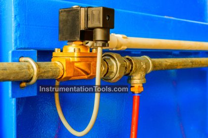
Air Lock is used when it is required to automatically hold the air pressure in control valve diaphragm chamber of the actuator, in an event of failure of air supply.

When supply pressure drops below a preset value, the Air Lock Relay locks the air pressure in the diaphragm chamber of the actuator thereby holding the control valve in the same position, till the air supply is resumed.

Control Valve Air Lock Relay Principle

Air Lock Relay Working Principle

The pneumatic lock-up valve or air lock relay shuts off the signal pressure line either when the air supply falls below an adjusted value or upon complete air supply failure. This causes the pneumatic actuator to remain in its last position.

The supply air produces a force on the diaphragm (4) which is balanced by the spring (6). When the force produced on the diaphragm is greater than the spring force, input and output are connected, i.e. the signal pressure supplied by the positioner is transmitted unobstructed to the pneumatic actuator.

When the supply air pressure falls below the adjusted value, the spring force dominates, and the spring (6) moves the plug (3) fully into the seat (9). As a result, the pressure in the pneumatic actuator is blocked.

control valve air lock relay Principle

Image Courtesy : Samson

Air Lock Relay Parts

  1. Body
  2. Cover
  3. Plug
  4. Diaphragm
  5. Screw for set point adjustment
  6. Spring
  7. Lock nut
  8. Cap
  9. Seat
  • pz : Supply air
  • pe : Input
  • pa : Output

Air Lock Cut Off Setting

The cut-off is sat to a desired value by compressing the spring by spring adjusting screw. If the actuator pressure range is 0.2-1.0 Kg/cm², the setting of this relay could be much higher than 1.0 Kg/cm² as desired for cut off. Where many control loops are involved, the setting of this relay therefore needs impulse connection for cut off from the air supply header.

Cut off setting has been factory adjusted to the desired cut off value. Should it be required to re-adjust the cut off setting, this could be achieved either while the unit is already installed and connected to the system or separately on the test bench. Inlet supply air and the outlet output gauge should be available to re-adjust the setting.

To adjust the cut off setting, remove cap and adjust spring adjusting screw until desired outlet cut off pressure is achieved. Please note that air lock pressure differential is approx. 0.17 Kg/cm² higher than the set cut off pressure.

Turning the adjusting screw clock-wise will increase the cut off setting and turning anti-clockwise will reduce the cut off setting.

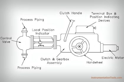
In this relay, a built-in manual relief valve is provided if the control valve has manual hand wheel. This exhausts the air from the diaphragm chamber when the hand wheel is operated to avoid damage to the actuator diaphragm.

Replace cap securely after having re-adjusting the cut off setting.

Applications :

Valve Air Lock Relay Applications

Parts : 

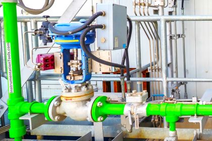
  1. Pneumatic control valve
  2. Positioner
  3. Air Lock Relay / Lock-up valve
  4. Solenoid valve

Source : Samson

Articles You May Like :

SIS Final Control Elements

JT Valve Working Principle

Control Valve Position

Pneumatic Valve Questions

Components of Shutdown Valve

Don't Miss Our Updates
Be the first to get exclusive content straight to your email.
We promise not to spam you. You can unsubscribe at any time.
Invalid email address
You've successfully subscribed !

Continue Reading

Valve Actuator Bench Set
SIS Final Control Elements
What is a Pneumatic Cylinder?
Instrumentation Inspection Report
What is a 4-way Solenoid Valve?
Valve Basics, Sizing, and Actuators Books
Share This Article
Facebook Whatsapp Whatsapp LinkedIn Copy Link
Share
9 Comments
  • tanmay kumar behera says:
    February 25, 2018 at 5:50 am

    please sir help me to save the document

    Reply
    • S Bharadwaj Reddy says:
      February 25, 2018 at 3:39 pm

      Step by Step Procedure sent to your email. Please check.

      Reply
      • venkataramana.k says:
        September 8, 2018 at 6:54 am

        Dear sir
        This is venkataramana from Kuwait KNPC we have a problem for flow control valve air fail to lock ,when air fail valve not lock on desire value it’s getting close. set the cut-off and relay screw adjusted but not stay air in actuator chamber, can you please solve my problem, functioning not good.

        Reply
  • Natrajan says:
    September 11, 2018 at 1:50 pm

    You can use airlock relay between positioner to actuator tubing so that at air fail condition if the air lock relay is working it will hold the pressure in the actuator and the valve position will remain undisturbed.

    Reply
  • vijay says:
    April 27, 2019 at 3:37 pm

    Apart from Relieving type is there built in relief to over pressurization in Air Filter/Regulator.

    Reply
  • Swapnil says:
    June 25, 2021 at 2:10 pm

    If Air Lock relay fails in any condition then will it be stayput or it will release air?

    Reply
  • Greg Osanebi says:
    August 6, 2021 at 11:52 pm

    Good day Instrument Engineers and SMEs, I have a question, My question is about a ring and Pinion Bettis Actuator Installed with a ball Ball Valve and also a Bettis Series G Actuator Installed with Ball Valve, Air is Supplied to these actuators and the Supply line for air is Isolated and the systems were commissioning for Process gas to flow via the Pipe Headers how long can the actuator and Valve keep being in open Position without a dedicated air supply, as the actuator configurations are Fail to close.

    In practice in an oil and gas flow station, it is a must for a dedicated air supply via an air compressor, but in this case, the project design engineer for SPDC is introducing this methodology using Nitrogen supply to open and the valves and lockout the supply from the nitrogen via ball valve installed in the tubing’s lines to the Valves. please I need urgent answers

    Reply
  • Alam says:
    December 28, 2022 at 11:46 am

    Dear Sir

    How to check pop-up for PSV relief valve. Please let me know.

    Reply
  • satya g says:
    July 15, 2024 at 5:46 pm

    hi gentlemen,
    can i bypass the Airlock valve without removing ?

    Reply

Leave a Reply Cancel reply

Your email address will not be published. Required fields are marked *

Stay Connected

128.3kFollowersLike
69.1kFollowersFollow
210kSubscribersSubscribe
38kFollowersFollow

Categories

Explore More

What is a Pneumatic Actuator ?
Control Valve Tips and Tricks
How to Select Control Valve Failure Mode
Types of Check Valves
Classification of Control Valves
Solenoid Valve with Manual Reset Working Principle
Relative Flow Capacity of a Valve
How to Choose a Control Valve?

Keep Learning

Pneumatic Piping Design and Specification

Pneumatic Piping Design and Specification

Pinch Valve

What is Pinch Valve ?

On-OFF Valve Animation

What is ON/OFF Valve ?

Interview Questions on Control Valves

Interview Questions on Control Valves

Safety Valve

Compare Relief Valve and Safety Valve

3-way solenoid valves control instrument air pressure

Solenoid Valve’s Energized or De-energized State ?

Control Valve Whisper Trim Cage

Problem with Choked Control Valve with Whisper Trim Cage

The Control Valve Stroke Test Procedure

Control Valve Stroke Test Procedure

Learn More

transmitters shared for BPCS and SIS

SIS Instrument Sharing – Transmitters Shared for BPCS and SIS Example

Pressure and Instrumentation MCQ - Questions & Answers

Pressure and Instrumentation MCQ – Questions & Answers

Standard Colors in PLC Automation Systems

Standard Colors in PLC Automation Systems

100+ Quiz on Electrical Circuits and Control

100+ Quiz on Electrical Circuits and Control

Vehicle Electrical Batteries upgrade

Upgrading the Electrical System in an Automobile

Control Valve Parts

Basic Parts of Control Valves

Pneumatic Level Control Valve

Piping and Instrumentation Drawing (P&ID) Tutorials – Part 3

RC snubber circuits

How Snubber Circuit works ?

Menu

  • About
  • Privacy Policy
  • Copyright

Quick Links

  • Learn PLC
  • Helping Hand
  • Part Time Job

YouTube Subscribe

Follow US
All rights reserved. Reproduction in whole or in part without written permission is prohibited.
Welcome Back!

Sign in to your account

Username or Email Address
Password

Lost your password?