This article has two objectives: to outline the basic process and key issues in planning, design, construction, and commissioning of a PLC or DCS Control System; and to summarize key points from the rest of the technical manual in a way that can serve as a checklist for the facility manager during the implementation process.
Control System Project Planning
The implementation process may be considered to include the following six stages. Each of these stages contains key milestones that must be met and issues that must be addressed and resolved before moving on to the next stage.
- Project team selection
- Project initiation
- Requirements definition
- System design
- Construction
- Commissioning

Project team selection
The following key personnel or their representatives make up the recommended project implementation team. Although time commitment and degree of involvement will vary with the stage of the project, all team members should be involved from the planning stage and remain in the communications loop throughout the duration of the project.
It is a mistake to delay the involvement of maintenance staff or the commissioning agent until the end of the design stage or the construction stage; making changes at this late stage based on their input will undoubtedly impact schedule and cost. If the procurement method used allows it, involving the installing contractor(s) from the start is also beneficial.
- Project manager
- Facility manager
- Operations and maintenance manager
- Controls technician
- Mission commander
- Utility system designer(s)
- PLC or DCS system designer
- Physical security specialist
- Information security specialist
- Reliability analyst
- Commissioning agent
Project initiation
The objective of the project initiation stage is to assemble the team, focus them on the objectives of the project as a common mission, and put in place the tools necessary for the team to accomplish that mission.
Specific tasks that must be accomplished for the project to move forward effectively include:
- Define the project scope and schedule.
- Establish the communication processes to be followed.
- Establish a document management system.
- Establish a process for tracking issues and documenting their resolution.
Requirements definition
The objective of the requirements definition stage is to clearly define the criteria which will serve as the basis for the design of the system. The result should be a written design basis document against which the design can be verified as it progresses.
Meeting the criteria defined in this stage becomes the primary measure of the technical success of the project.
a. Top-level criteria:
- Reliability, Availability, Maintainability (RAM) criteria
- Configuration and level of redundancy matched to system design
- Type of HMI and extent of manual control capability matched to staffing levels and qualifications
- Established design standards
- Physical security policies
- Information/network security policies
b. Detail level criteria:
- Systems sequence of operations/control strategy clearly defined
- Required failure states of all valves and other equipment identified
- Define all contingency conditions to be protected against
- Determine data presentation format, number of screens, etc.
- Physical security provisions defined
- Information/network security provisions defined
Design
The objective of the design stage is to translate the design basis document into system design and document the design clearly and completely so that it can be constructed properly, commissioned completely, and operated and maintained reliably and efficiently.
The primary criteria for design documents should be the completeness of detail and clarity of design intent. The system should be fully designed during this stage, where the careful review can take place, rather than leaving details to be “worked out” in the field during construction and commissioning.
a. Key issues to be addressed in this stage include:
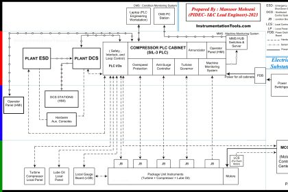
(1) Develop a system architecture schematic or block-diagram drawing.
(2) Select network communications media (fiber optic, etc.) appropriate to the physical and electrical environments.
(3) Analyze the proposed architecture to verify it meets the RAM criteria.
(4) Select system vendor(s) and hardware considering;
- In-service history
- Vendor support
- RAM data
- Staff experience
b. Detailed design documents should be formally reviewed by all team members at established points in the design process. The number of review submittals may vary with the size and complexity of the project, but a minimum of two submittals prior to completion is recommended.
These reviews should verify the following:
(1) All symbols, abbreviations and line types are clearly defined.
(2) A complete and consistent equipment and cable identification (tag number) scheme is used.
(3) Loop and Binary Logic Diagrams or Descriptions are provided.
(4) A complete input/output points list has been provided.
(5) Open protocols and readily available hardware are specified.
(6) Design has been analyzed for reliability, availability and maintainability criteria.
(7) Power supplies match system RAM and redundancy levels.
(8) Physical segregation exists between redundant components and paths.
(9) Layout of operator controls and indicators and HMI screens has been clearly specified for human factors considerations.
(10) Environmental protection level of devices and enclosures is clearly specified and appropriate for their location.
(11) The design of the grounding and surge protection system is clearly detailed and specified.
(12) Control equipment is located within secure spaces.
(13) External communication links are secure.
(14) The design includes all test and measurement provisions needed for commissioning.
(15) All components can be tested and maintained without interrupting the mission.
(16) Physical security provisions are clearly defined.
(17) Information/network security provisions are clearly defined.
Construction
The objective of the construction stage is to install and place into operation the PLC or DCS system hardware and software in compliance with the design documents.
This stage should utilize standard construction management tools and techniques for managing schedule, cost, contract changes, etc. However, for a PLC or DCS project, there are some additional considerations that must be addressed:
a. A change management process should be established assuring that all field issues receive the appropriate technical review.
b. All changes should be documented on an ongoing basis, and design documents kept current, rather than leaving this to an end-of-project “as-built drawings” task.
c. Operations and maintenance data should be assembled and reviewed during the construction process and must be completed prior to commissioning.
Commissioning
The objective of the commissioning stage is to obtain formal verification that the installed control system complies with and performs in accordance with the design intent as defined in the Design Basis and the detailed design documents.
Key aspects of commissioning include:
a. Preparation of a commissioning plan.
b. Factory acceptance testing of PLC hardware and software.
c. Integrity testing of installed devices and conductors.
d. Instrument calibration and loop verification.
e. Preparation and review of test procedures.
f. Functional performance testing.
g. Verification of physical and information/network security provisions.
h. Verification of complete system documentation.
Join the Discussion
Share & leave us some comments on what you think about this topic or if you like to add something.
Reference: This material adapted from the “Department of the Army, TM 5-601, Supervisory Control and Data Acquisition (SCADA) Systems for Command, Control, Communications, Computer, Intelligence, Surveillance, and Reconnaissance (C4ISR) Facilities, 21 January 2006.”
Read Next:
- Commissioning Documents
- Architecture of Instrumentation
- What is PID Controller?
- Alarm Management Practices
- Examples of SCADA and PLC





thanks