PLC ladder logic design to control 3 motors with toggle switch and explain the program using the video & article.
Note: This example ladder logic is for education purposes and for practicing PLC programming.
Control 3 Motors with Toggle Switch
Problem Statement:
Design a PLC ladder logic for the following application.
We are using one toggle switch to control 3 Motors.
When the Start Button is ON,
The First Stage Motor runs for 10 seconds, then stops.
After a 5-second delay, the Second Stage Motor runs for 20 seconds and then the Third Stage Motor will run for 15 seconds.
PLC Basics for Beginners
You can learn the PLC basics easily from our programming examples for beginners.
This video explains the given PLC problem statement with a detailed solution.
Inputs and Outputs
Digital Inputs:
Start Button: I0.0
Digital Outputs:
Motor 1: Q0.0
Motor 2: Q0.1
Motor 3: Q0.2
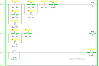
PLC Ladder Logic Design
Program Description
We have used Normally Open Contact for the Start Button(I0.0).
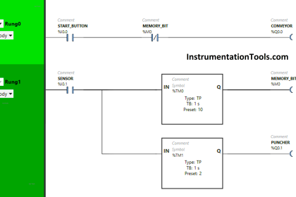
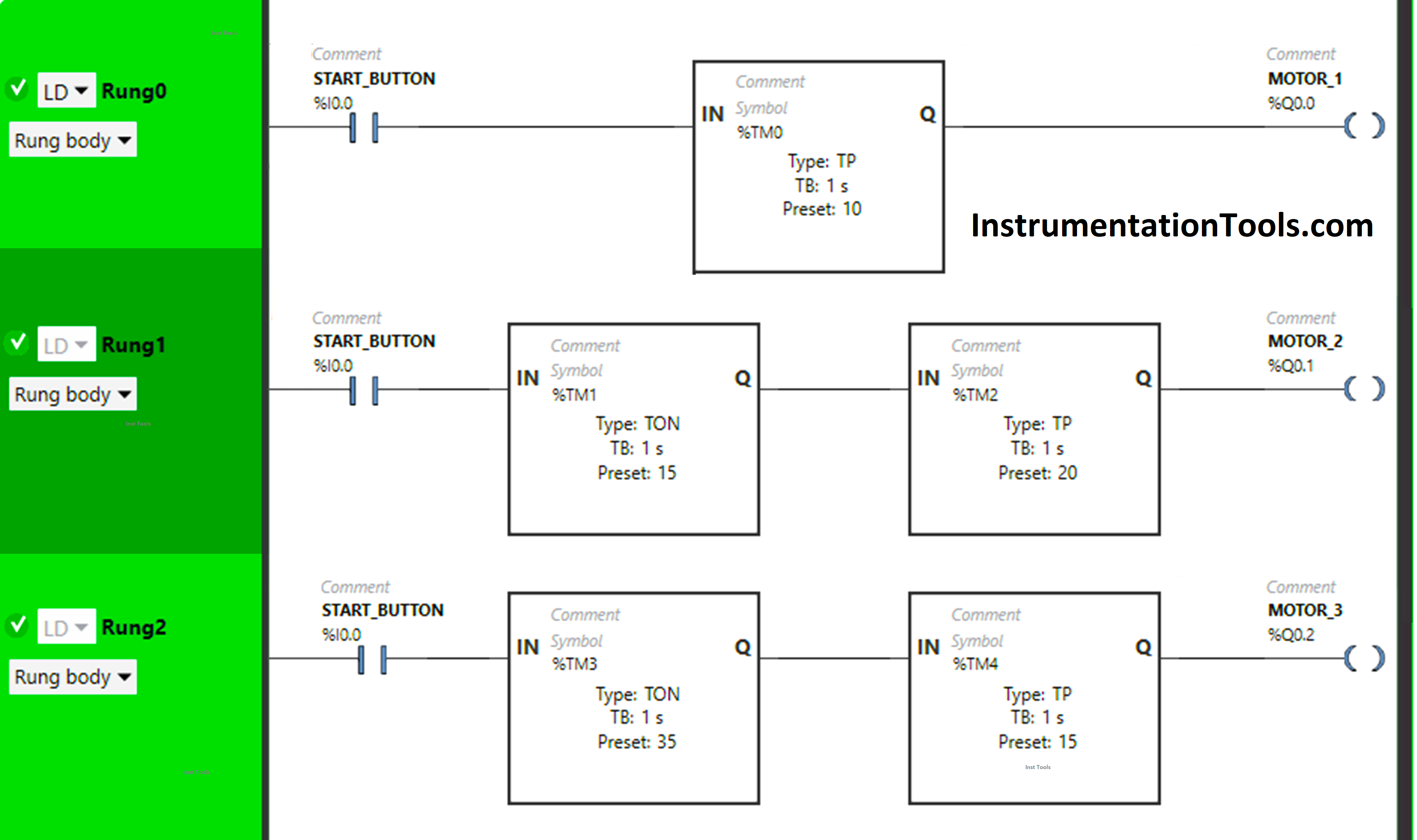
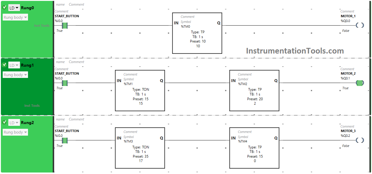
In Rung 0:
- Normally Open Contact is used for the Start Button (I0.0) to Turn ON the output Motor 1 (Q0.0).
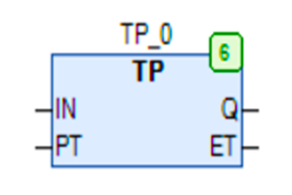
- TP timer is used to Turn ON the output Motor 1 (Q0.0) for a limited time.
In Rung 1:
- Normally Open Contact is used for the Start Button (I0.0) to Turn ON the output Motor 2 (Q0.1).
- TON timer is used to delay the turning ON time of the output Motor 2 (Q0.1) for some time.
- TP timer is used to Turn ON the output Motor 2(Q0.1) for a limited time.
In Rung 2:
- Normally Open Contact is used for the Start Button (I0.0) to Turn ON the output Motor 3 (Q0.2).
- TON timer is used to delay the turning ON time of the output Motor 3 (Q0.2) for some time.
- TP timer is used to Turn ON the output Motor 3 (Q0.2) for a limited time.
Simulated Logic
Now we will simulate our program and see the test cases.
Rung 0:
When the Start Button (I0.0) is turned ON, the signal will flow through the Start Button as Normally Open Contact is used for the Start Button (I0.0).
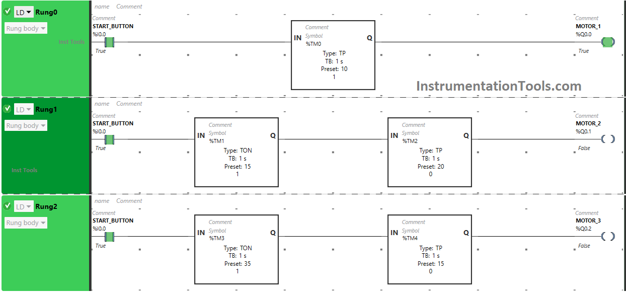
The output Motor 1 (Q0.0) turns ON for 10 seconds because Timer Function Block type TP is used to turn ON the output Motor 1 (Q0.0) for a limited time and the time is set to 10 seconds. After 10 seconds, the output Motor 1 (Q0.0) will turn OFF.
Rung 1:
When the Start Button is turned ON, Motor2 (Q0.1) will turn ON after 15 seconds ( i.e after 5 seconds when Motor 1 gets turned OFF) because Timer Function Block type TON is used to delay the turning ON time of the output Motor 2 (Q0.1) and the time is set to 15 seconds.
The output Motor 2 (Q0.1) will remain ON only for 20 seconds as we have used Timer Function Block type TP to turn ON the output Motor 2 (Q0.1) only for a limited time and the time is set to 20 seconds. So after 20 seconds, the output Motor 2 (Q0.1) will turn OFF.
Rung 2:
When the Start Button is turned ON, Motor 3 (Q0.2) will turn ON after 35 seconds ( i.e immediately when Motor 2 gets turned OFF) because Timer Function Block type TON is used to delay the turning ON time of the output Motor 3 (Q0.2) and the time is set to 35 seconds.
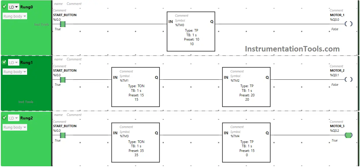
The output Motor 3 (Q0.2) will remain ON only for 15 seconds as we have used Timer Function Block type TP to turn ON the output Motor 3 (Q0.2) only for a limited time and the time is set to 15 seconds. So after 15 seconds, the output Motor 3 (Q0.2) will turn OFF.
If you liked this article, please subscribe to our YouTube Channel for PLC and SCADA video tutorials.
You can also follow us on Facebook and Twitter to receive daily updates.
Read Next:
- Example of PLC Timer Programming
- PLC Programming for Elevator Stop Logic
- PLC Programming on Bottle Line Control
- Conveyor and Puncher PLC Programming
- Batch Mixing PLC Ladder Logic Program