Inst ToolsInst ToolsInst Tools
  • Courses
  • Automation
    • PLC
    • Control System
    • Safety System
    • Communication
    • Fire & Gas System
  • Instrumentation
    • Design
    • Pressure
    • Temperature
    • Flow
    • Level
    • Vibration
    • Analyzer
    • Control Valve
    • Switch
    • Calibration
    • Erection & Commissioning
  • Interview
    • Instrumentation
    • Electrical
    • Electronics
    • Practical
  • Q&A
    • Instrumentation
    • Control System
    • Electrical
    • Electronics
    • Analog Electronics
    • Digital Electronics
    • Power Electronics
    • Microprocessor
  • Request
Search
  • Books
  • Software
  • Projects
  • Process
  • Tools
  • Basics
  • Formula
  • Power Plant
  • Root Cause Analysis
  • Electrical Basics
  • Animation
  • Standards
  • 4-20 mA Course
  • Siemens PLC Course
Reading: Comparison of Proportional Integral Derivative Controllers (PID)
Share
Font ResizerAa
Inst ToolsInst Tools
Font ResizerAa
  • Courses
  • Design
  • PLC
  • Interview
  • Control System
Search
  • Courses
  • Automation
    • PLC
    • Control System
    • Safety System
    • Communication
    • Fire & Gas System
  • Instrumentation
    • Design
    • Pressure
    • Temperature
    • Flow
    • Level
    • Vibration
    • Analyzer
    • Control Valve
    • Switch
    • Calibration
    • Erection & Commissioning
  • Interview
    • Instrumentation
    • Electrical
    • Electronics
    • Practical
  • Q&A
    • Instrumentation
    • Control System
    • Electrical
    • Electronics
    • Analog Electronics
    • Digital Electronics
    • Power Electronics
    • Microprocessor
  • Request
Follow US
All rights reserved. Reproduction in whole or in part without written permission is prohibited.
Inst Tools > Blog > Control Systems > Comparison of Proportional Integral Derivative Controllers (PID)

Comparison of Proportional Integral Derivative Controllers (PID)

The components of a PID controller - Proportional (P), Integral (I), and Derivative (D) each have distinct characteristics and applications.

Last updated: September 20, 2023 10:19 am
Editorial Staff
Control Systems PLC Tutorials
No Comments
Share
3 Min Read
SHARE

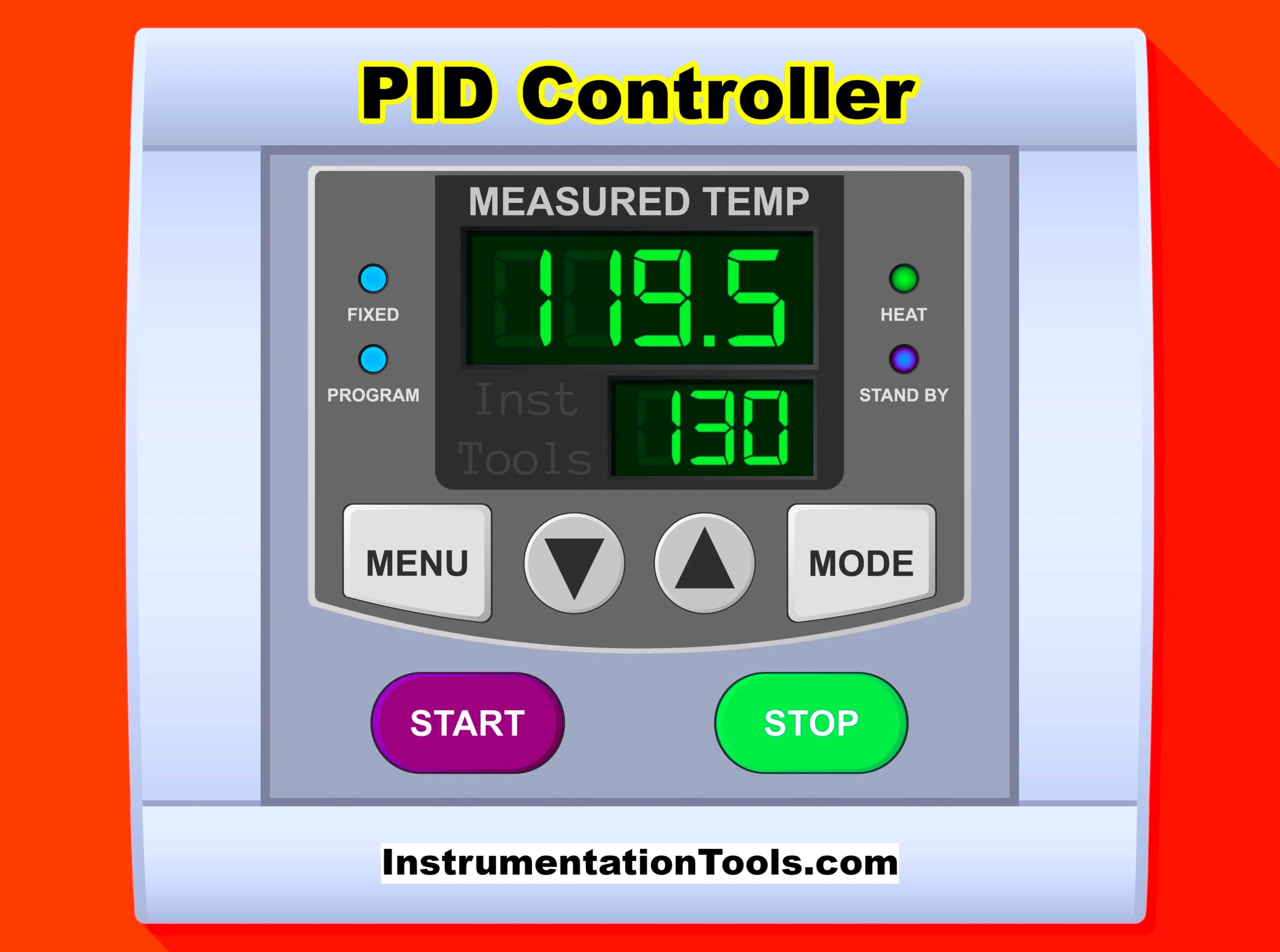
The components of a PID controller – Proportional (P), Integral (I), and Derivative (D) each have distinct characteristics and applications. These controllers can also be used independently or in combinations like PI, PD, etc.

Comparison of Proportional Integral Derivative Controllers

Comparison of Proportional Integral Derivative Controllers (PID)

The following table shows the differences between the P, I, and D controller functions.

ParameterP ControllerI ControllerD Controller
Principle of OperationProportional to errorIntegral of errorDerivative of error
Error EliminationSteady-state errorEliminates steady-state errorDoes not eliminate any error
StabilityModerateMay reduce stabilityIncreases stability
OvershootModerateHighLow
Response TimeFastSlowFast
System Type SuitabilityFirst order systemsSystems with steady-state errorsSystems requiring damping
Implementation ComplexityLowModerateModerate
CostLowModerateModerate
Application ExamplesLevel control, temperature controlCruise control, HVACDamping control, robotics
Tuning ComplexityLowModerateModerate
Control ActionProportional to present errorBased on accumulated past errorsPredictive, based on rate of error change

Explanation of the terms:

  • Principle of Operation: The mathematical relationship that dictates how each controller type reacts to the error signal.
  • Error Elimination: How effective the controller is at eliminating system error.
  • Stability: How the controller affects the system’s stability.
  • Overshoot: The extent to which the system exceeds its setpoint.
  • Response Time: How quickly the controller reacts to an error.
  • System Type Suitability: Types of systems where each controller is most effective.
  • Implementation Complexity: The complexity involved in implementing each type of control.
  • Cost: The relative cost of implementing each control type.
  • Application Examples: Common applications where each type of control is often used.
  • Tuning Complexity: How difficult it is to tune the parameters for optimal performance.
  • Control Action: Describes what aspect of the error signal the controller acts upon.

If you liked this article, then please subscribe to our YouTube Channel for Instrumentation, Electrical, PLC, and SCADA video tutorials.

You can also follow us on Facebook and Twitter to receive daily updates.

Read Next:

  • Compare Hardwired I/O and Serial I/O
  • Difference Between PNP and NPN Sensor
  • Light Tower in Industrial Automation
  • Learn about PLC, DCS, RTU, SCADA
  • Programming and Tuning PID Controller
Don't Miss Our Updates
Be the first to get exclusive content straight to your email.
We promise not to spam you. You can unsubscribe at any time.
Invalid email address
You've successfully subscribed !

Continue Reading

PID in Studio 5000
PLC Program for Star Delta Motor Starter
Understanding Braking Theory in VFD
Procedure for Reading or Searching the Tag number in Siemens PLC
PLC Program for Artificial Fishpond Water Level Monitoring System
Tank Farm Management System: CX-Programmer [OMRON]
Share This Article
Facebook Whatsapp Whatsapp LinkedIn Copy Link
Share
Leave a Comment

Leave a Reply Cancel reply

Your email address will not be published. Required fields are marked *

Stay Connected

128.3kFollowersLike
69.1kFollowersFollow
210kSubscribersSubscribe
38kFollowersFollow

Categories

Explore More

PLC Program to Simulate Gate Array Logic
PLC Program for Trash Compactor
Instrumentation and Electrical Teams Interactions (Detail Design Engineering)
PLC Project Examples for EcoStruxure Machine Expert
Allen Bradley PLC Subroutines
Industrial Automation and Control Systems (IACS)
Parallel Tanks Level Control using PLC Ladder Diagram Tutorial
Control System Architecture

Keep Learning

Python in Industrial Automation

Python in Industrial Automation and Control Systems

How to Prevent Ground Loops in Analog Circuits?

How to Prevent Ground Loops in Analog Circuits?

4 TO 20 MA ANALOG CURRENT SIGNALS

Basics of 4 to 20 mA analog Signals

PLC Data comparison instructions

PLC Data Comparison Instructions

What is a Wet Contact in PLC

What is a Wet Contact? – Basics of PLC Wiring

Free WinCC SCADA Training Course

Free SCADA Training Course

System Architecture in Industrial Automation

How to Design a System Architecture in Industrial Automation?

PLC PID tuning parameters

Programming and Tuning PID Controller in PLC – Siemens TIA Portal

Learn More

Chromatography Questions & Answers

Operation of Chromatography Questions & Answers

Root Locus Concepts Objective Questions

Root Locus Concepts Objective Questions

Track PLC Operating Modes

#2 PLC Best Practices – Track Operating Modes

Electrical & Electronics Measurements Objective Questions

Electrical & Electronics Measurements Objective Questions – Set 1

Power Systems Questions & Answers

Power Systems MCQ Series 18

SCADA Standards

SCADA for Substation Automation

Sensors and Transducers Test

Sensors and Transducers Test

Types of Motor Enclosures

Types of Motor Enclosures

Menu

  • About
  • Privacy Policy
  • Copyright

Quick Links

  • Learn PLC
  • Helping Hand
  • Part Time Job

YouTube Subscribe

Follow US
All rights reserved. Reproduction in whole or in part without written permission is prohibited.
Welcome Back!

Sign in to your account

Username or Email Address
Password

Lost your password?