Inst ToolsInst ToolsInst Tools
  • Courses
  • Automation
    • PLC
    • Control System
    • Safety System
    • Communication
    • Fire & Gas System
  • Instrumentation
    • Design
    • Pressure
    • Temperature
    • Flow
    • Level
    • Vibration
    • Analyzer
    • Control Valve
    • Switch
    • Calibration
    • Erection & Commissioning
  • Interview
    • Instrumentation
    • Electrical
    • Electronics
    • Practical
  • Q&A
    • Instrumentation
    • Control System
    • Electrical
    • Electronics
    • Analog Electronics
    • Digital Electronics
    • Power Electronics
    • Microprocessor
  • Request
Search
  • Books
  • Software
  • Projects
  • Process
  • Tools
  • Basics
  • Formula
  • Power Plant
  • Root Cause Analysis
  • Electrical Basics
  • Animation
  • Standards
  • 4-20 mA Course
  • Siemens PLC Course
Reading: Comparator in PLC Programming
Share
Font ResizerAa
Inst ToolsInst Tools
Font ResizerAa
  • Courses
  • Design
  • PLC
  • Interview
  • Control System
Search
  • Courses
  • Automation
    • PLC
    • Control System
    • Safety System
    • Communication
    • Fire & Gas System
  • Instrumentation
    • Design
    • Pressure
    • Temperature
    • Flow
    • Level
    • Vibration
    • Analyzer
    • Control Valve
    • Switch
    • Calibration
    • Erection & Commissioning
  • Interview
    • Instrumentation
    • Electrical
    • Electronics
    • Practical
  • Q&A
    • Instrumentation
    • Control System
    • Electrical
    • Electronics
    • Analog Electronics
    • Digital Electronics
    • Power Electronics
    • Microprocessor
  • Request
Follow US
All rights reserved. Reproduction in whole or in part without written permission is prohibited.
Inst Tools > Blog > PLC Tutorials > Comparator in PLC Programming

Comparator in PLC Programming

Last updated: March 4, 2021 3:29 pm
Editorial Staff
PLC Tutorials
No Comments
Share
5 Min Read
SHARE

To study the working of comparator blocks (EQU, NEQ, LES, GRT, LEQ and GEQ) using simple example in Allen Bradley programmable logic controllers (PLC).

Contents
Ccomparator in PLCDescription of Comparator Blocks :Program LogicPLC Input Output ListPLC Comparator ProgrammingLogic Description:Conclusion

Ccomparator in PLC

Ccomparator in PLC Programming

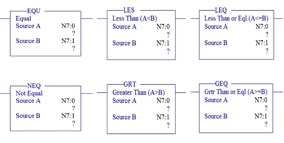
There are two parameter in each block,

Source A & Source B –where values are stored.

Description of Comparator Blocks :

EQU :

 Equal block is used to compare the two values stored in Source A and source B and gives output as “1” if both are equal and “0” if both are not equal.

LES :

Lesser than block is used to compare the two values stored in Source A and source B and gives output as “1” if  Source A value is Lesser than Source B value and “0” if Source A value is greater  than  or equal to Source B value.

LEQ :

Lesser than or equal to   block is used to compare the two values stored in Source A and source B and gives output as “1” if Source A value is lesser than or equal value to Source B value and “0” if Source A value is greater Source B value.

NEQ :

Not equal  block is used to compare the two values stored in Source A and source B and gives output as “1” if  Source A value is not same as  Source B value and “0” if Source A value is same as Source B value.

GRT :

Greater than  block is used to compare the two values stored in Source A and source B and gives output as “1” if  Source A value is Greater than Source B value and “0” if Source A value is lesser than  or equal to Source B value.

GEQ :

Greater than or equal to  block is used to compare the two values stored in Source A and source B and gives output as “1” if Source A value is Greater than or equal value to Source B value and “0” if Source A value is Lesser Source B value.

Let us understand the working of comparator block using simple example,

Program Logic

When start switch is pressed,

  1. If water level is below 5, motor should turn ON till water level reach 95.
  2. If water level indicates the value below 5, low level water alarm should ON.
  3. If water level indicates the value above 95, high level water alarm should ON.
  4. If water level is exactly at 95, steamer should turn ON.
  5. System under control indication should always ON when water level is not equal to 100.

PLC Input Output List
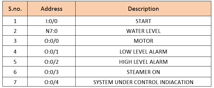
PLC input output list for water tank

PLC Comparator Programming

PLC Programming Comparator examples

Logic Description:

RUNG 0000

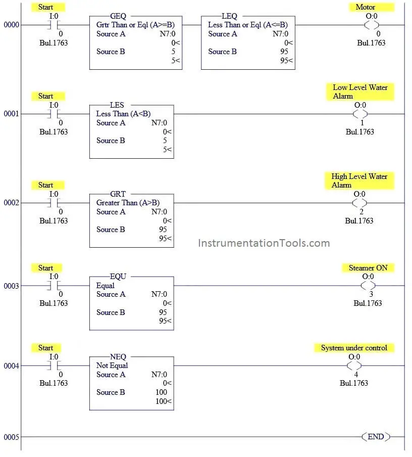
When Start switch is pressed,N7:0 is the water level value which is compared with 5 and 95 using GEQ and LEQ block to turn ON Motor.(i.e-Motor should turn ON if water level is between 5 and 95)

RUNG 0001

Low level alarm is triggered, when water level goes below 5.Less than block is used to perform this function.

RUNG 0002

High level alarm is triggered, when water level goes above 95.Greater than (GRT) block is used to perform this function.

RUNG 0003

Steamer output is turned ON when water level reached exactly at 95.

RUNG 0004

System under control output always in ON condition when water level is not at 100.

Conclusion

We can use this example program to understand the working comparator block function in Allen Bradley programmable logic controllers (PLC).

Author : Hema Sundaresan

If you liked this article, then please subscribe to our YouTube Channel for PLC and SCADA video tutorials.

You can also follow us on Facebook and Twitter to receive daily updates.

Read Next:

PLC Questions and Answers

Allen Bradley Interview Questions
Basics of PLC Programming

Distributed Control Systems

PLC Math instructions

Don't Miss Our Updates
Be the first to get exclusive content straight to your email.
We promise not to spam you. You can unsubscribe at any time.
Invalid email address
You've successfully subscribed !

Continue Reading

Siemens PLC programming: BCD, Integer, Double Integer, Real
DCS versus PLC Architecture
Create a Function (FC) for a Valve Logic in Siemens PLC
PLC based 4 Way Traffic Light Control System
Step by Step Guidelines for Downloading Free PLC software
PLC Analog Input Sampling Ladder Logic
Share This Article
Facebook Whatsapp Whatsapp LinkedIn Copy Link
Share
Leave a Comment

Leave a Reply Cancel reply

Your email address will not be published. Required fields are marked *

Stay Connected

128.3kFollowersLike
69.1kFollowersFollow
210kSubscribersSubscribe
38kFollowersFollow

Categories

Explore More

PLC Mixing Logic in Liquids on EcoStruxure Machine Expert-Basic
3 to 8 Line Decoder PLC Ladder Diagram
Industrial Automation Pre-Engineering Design Documents – Project & Process
PLC Sizes and Applications
Network Switch Port Allocation Details
Free Industrial Control System (ICS) Cyber Security Training Course
How to Delay a Sensor Signal in PLC?
Normally-open and Normally-closed Switch Contacts

Keep Learning

PLC Logic for Stairway Lighting

Smart Automation Solutions: PLC Logic for Stairway Lighting

PLC program to control a water pump

PLC Program to Control a Water Pump

PLC Timers with Practical Examples

Omron PLC Timer Example Explained

PLC Structured Text Program for Light Sequences via Timers

PLC Structured Text Program for Light Sequences via Timers

relay-safety-in-plc

How to Reduce Relay Noise in PLC Systems?

Learn about PLC, DCS, RTU, SCADA, and PAC

Learn about PLC, DCS, RTU, SCADA, and PAC

PLC Code to Start & Stop Motor and Pump as per Logic

PLC Code to Start & Stop Motor and Pump as per Logic

Allen Bradley PLC communication is established

Procedure for Connecting Allen Bradley PLC and PC – RS Logix 500

Learn More

Two Electrode Conductivity Probes

Two Electrode Conductivity Probes Principle

IR Radio Sensors Objective Questions

IR Radio Sensors Objective Questions

Non‐contact RADAR Level Transmitter Pulse

Non Contact RADAR Level Transmitter Principle, Limitations, Design, Installation and Calibration

Calibration setup for a low-range electronic pressure transmitter

Instrument Lab Exercise – Ranging and Manometer Usage

Industrial Networking Interview Questions

Industrial Networking and Wireless Interview Questions

Tie rods double acting cylinder

What is a Pneumatic Cylinder?

11 kV, 3.3 kV, and 400 V systems insulation resistance (IR) Problems

11 kV, 3.3 kV, and 400 V systems insulation resistance (IR) Problems

DC Machine

DC Generator Internal Losses

Menu

  • About
  • Privacy Policy
  • Copyright

Quick Links

  • Learn PLC
  • Helping Hand
  • Part Time Job

YouTube Subscribe

Follow US
All rights reserved. Reproduction in whole or in part without written permission is prohibited.
Welcome Back!

Sign in to your account

Username or Email Address
Password

Lost your password?