Inst ToolsInst ToolsInst Tools
  • Courses
  • Automation
    • PLC
    • Control System
    • Safety System
    • Communication
    • Fire & Gas System
  • Instrumentation
    • Design
    • Pressure
    • Temperature
    • Flow
    • Level
    • Vibration
    • Analyzer
    • Control Valve
    • Switch
    • Calibration
    • Erection & Commissioning
  • Interview
    • Instrumentation
    • Electrical
    • Electronics
    • Practical
  • Q&A
    • Instrumentation
    • Control System
    • Electrical
    • Electronics
    • Analog Electronics
    • Digital Electronics
    • Power Electronics
    • Microprocessor
  • Request
Search
  • Books
  • Software
  • Projects
  • Process
  • Tools
  • Basics
  • Formula
  • Power Plant
  • Root Cause Analysis
  • Electrical Basics
  • Animation
  • Standards
  • 4-20 mA Course
  • Siemens PLC Course
Reading: CODESYS HMI Interface
Share
Font ResizerAa
Inst ToolsInst Tools
Font ResizerAa
  • Courses
  • Design
  • PLC
  • Interview
  • Control System
Search
  • Courses
  • Automation
    • PLC
    • Control System
    • Safety System
    • Communication
    • Fire & Gas System
  • Instrumentation
    • Design
    • Pressure
    • Temperature
    • Flow
    • Level
    • Vibration
    • Analyzer
    • Control Valve
    • Switch
    • Calibration
    • Erection & Commissioning
  • Interview
    • Instrumentation
    • Electrical
    • Electronics
    • Practical
  • Q&A
    • Instrumentation
    • Control System
    • Electrical
    • Electronics
    • Analog Electronics
    • Digital Electronics
    • Power Electronics
    • Microprocessor
  • Request
Follow US
All rights reserved. Reproduction in whole or in part without written permission is prohibited.
Inst Tools > Blog > PLC Tutorials > CODESYS HMI Interface

CODESYS HMI Interface

Learn how to design a standard CODESYS HMI interface and link it with the PLC program to learn the basics first.

Last updated: May 7, 2024 12:37 pm
Viral Nagda
PLC Tutorials
1 Comment
Share
5 Min Read
SHARE

Codesys is a platform that has been developed for industrial automation devices and has its own set of frameworks for graphics, screen layout, blocks, instructions, syntax, and other elements.

Any PLC manufacturer that uses Codesys can find this common layout and rules in other PLCs too that use Codesys. Nowadays, devices have come in Codesys which offer PLC programming along with HMI screens in the same hardware and platform. One such device is GOC43 of Mitsubishi Electric, which is a PLC cum HMI controller.

In this post, we will learn how to design a standard Codesys PLC program and link it internally with Codesys HMI visualizations by using this device as a reference. We will create a simple understandable program and not go deeper into the topic by just learning the basics first.

CODESYS HMI Interface

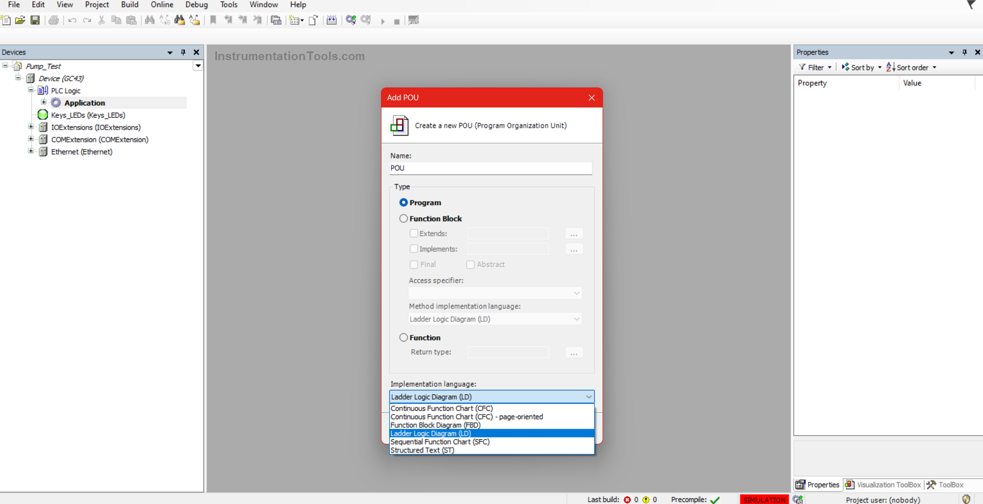
All the Codesys platforms have the following languages supported for PLC programming – continuous flow chart, function block diagram, ladder logic, sequential function chart, and instruction list.

You are provided with two options: create a section (program) or create a user-defined library (function block). It is referred to as POU (program organization unit). That means if you have created 10 sections of the program and function block, it means you have created 10 POU’s in the program.

CODESYS HMI Interface

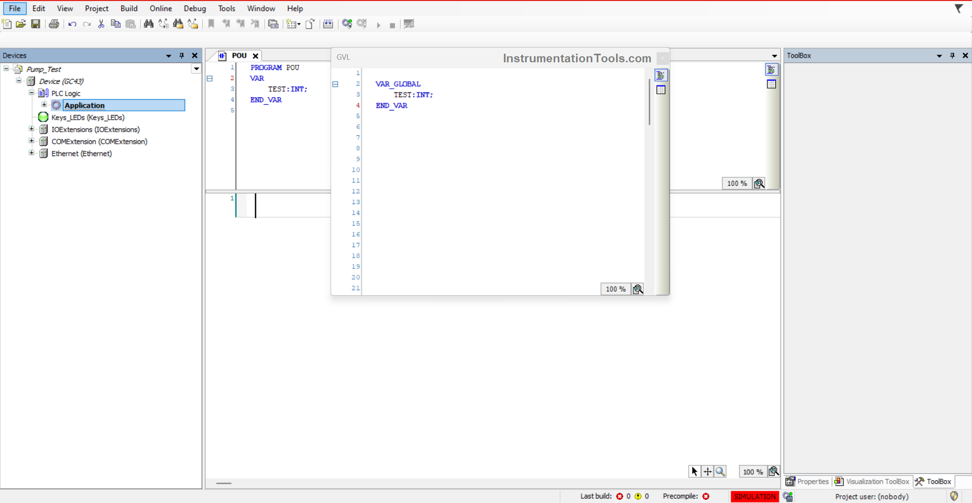
A variable can be defined in two scopes – local or global, as shown in the figure below. In the section we created, if we define a variable named test in the section itself, then it can be used locally in that section only.

Inversely, if we define this variable in GVL (global variable list), then it can be used in any section of the whole program.

CODESYS HMI Visualization

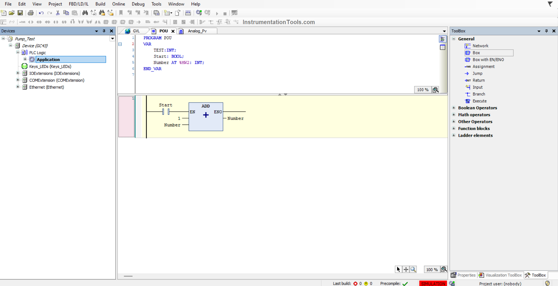
Now, suppose we define the variables locally in our example. Refer to the below image.

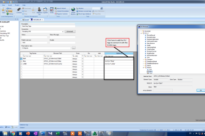
As you can see, the start variable has not been given a memory address, whereas the number variable has been given the memory address as %MW2. This means that the number variable can be accessed by an external device like HMI or other master controllers through this address.

Accordingly, you need to define variables as per your requirement, by either giving them an address or not. You can take the blocks and instructions from the right-hand side toolbox as shown.

CODESYS HMI PLC Implementation

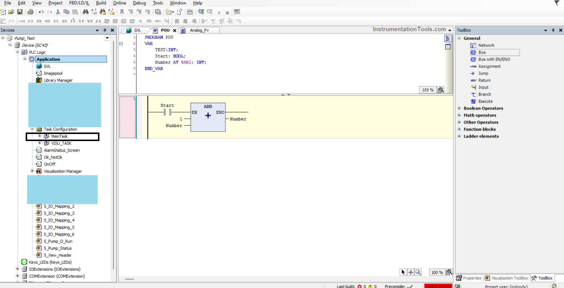
Then, you need to add the section we created in the task configuration as shown below with the black box. This will allow the PLC CPU to execute that logic. Otherwise, it will not be executed in the processor.

Creating an HMI in CODESYS

Now, we head on to the graphics part. As seen in the figure below, you have to add a visualization object, just like you added a POU object for PLC programming. This will create a screen. There, you can place the objects as per your requirements.

As you can see in the below image, on the right-hand side, it shows the properties of a rectangle object that I have placed. There, you can directly link the variables that you defined in the PLC program – like text variables, color variables, and state variables and also configure input action in input configuration.

HMI with CODESYS

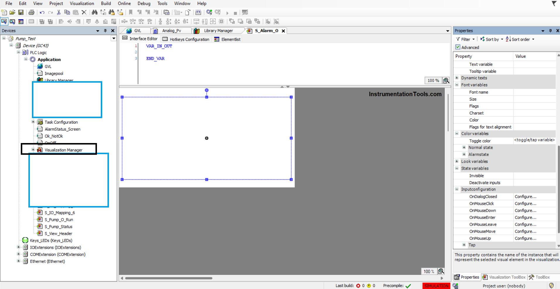
So, just create variables with any name in the PLC program and directly link in the objects wherever required.

In this way, we saw how to design a sample project involving PLC and HMI programming using Codesys software.

If you liked this article, then please subscribe to our YouTube Channel for Instrumentation, Electrical, PLC, and SCADA video tutorials.

You can also follow us on Facebook and Twitter to receive daily updates.

Read Next:

  • Download Free CODESYS Software
  • Learn about SCADA and HMI Systems
  • Difference between PLC and HMI Systems
  • Create an Application in HMI using the Tia Portal
  • What is CODESYS? Why Do You Need to Learn It?
Don't Miss Our Updates
Be the first to get exclusive content straight to your email.
We promise not to spam you. You can unsubscribe at any time.
Invalid email address
You've successfully subscribed !

Continue Reading

Open Source PLC and SCADA Software
Free Siemens PLC Training Course
Difference Between FC and FB in Tia Portal
Check Block Consistency Tools in Simatic Manager
ControlLogix Architecture – Rockwell Automation
Structured Text PLC Programming for Automatic Gate Control
Share This Article
Facebook Whatsapp Whatsapp LinkedIn Copy Link
Share
1 Comment
  • Arvin Mistry says:
    June 20, 2024 at 2:05 am

    Example must be completed in the same , Example tuterial, rather waiting for next vedio.

    Reply

Leave a Reply Cancel reply

Your email address will not be published. Required fields are marked *

Stay Connected

128.3kFollowersLike
69.1kFollowersFollow
210kSubscribersSubscribe
38kFollowersFollow

Categories

Explore More

Implement UDT in PLC Programming: User-Defined Data Type
Difference between Machine Expert Basic and Machine Expert – Schneider PLC
What is NOR Flash Memory in PLC?
PLC Programming Projects for Beginners
PLC Interview Questions and Answers
How to Configure an Alarm in InTouch SCADA?
How to Configure IP Address in Rockwell PLC?
Siemens S7 300 and STEP 7 PLC program using SIMATIC Software

Keep Learning

Principle of Operation of PLC

Principle of Operation of PLC

Automatic Box Filling System using PLC Programming

Automatic Box Filling System using PLC Programming

PLC and MCC Panel Interface Design

PLC Panel and MCC Panel Interface Signals

Automatic Liquid Mixing Application

PLC Program for Automatic Liquid Mixing Application

Comparator used in Siemens S7-1200 PLC.

Siemens PLC Comparator Logic

PLC Scan Time

PLC Scan Time

Conveyor Sorting Machine PLC Program

Conveyor Sorting Machine PLC Program with Calculation Function

PLC Documents

PLC System Documentation

Learn More

four-way-solenoid-valve-diagram

Four Way Solenoid Valve Working Principle

HART Protocol and Fieldbus Interview Questions

HART Protocol and Fieldbus Interview Questions

Failsafe interlock Design

Failsafe Wiring Practices

Resistance Temperature Detectors Errors

Resistance Temperature Detectors (RTD) Sources of Error

Advances in Control System

Fuzzy Logic Control

Objective Questions on Valves

Objective Questions on Valves

Analytical Measurement Multiple Choice Questions

Analytical Measurement Multiple Choice Questions

What is a Inductive Proximity Switch

What is a Inductive Proximity Switch ?

Menu

  • About
  • Privacy Policy
  • Copyright

Quick Links

  • Learn PLC
  • Helping Hand
  • Part Time Job

YouTube Subscribe

Follow US
All rights reserved. Reproduction in whole or in part without written permission is prohibited.
Welcome Back!

Sign in to your account

Username or Email Address
Password

Lost your password?