Inst ToolsInst ToolsInst Tools
  • Ask
  • Courses
  • Videos
  • Q & A
    • Interview
      • Instrumentation
      • Electronics
      • Electrical
      • Practical Questions
    • MCQ
      • Instrumentation MCQ
      • Electrical MCQ
      • Electronics MCQ
      • Control Systems MCQ
      • Analog Electronics MCQ
      • Digital Electronics MCQ
      • Power Electronics MCQ
      • Microprocessor MCQ
      • Multiple Choice Questions
  • EE
    • Electronics
      • Electronics Q & A
      • Electronic Basics
      • Electronic Devices & Circuits
      • Electronics Animation
      • Digital Electronics
    • Electrical
      • Electrical Basics
      • Electrical Q & A
      • Power Electronics
      • Electrical Machines
      • Electrical Animation
      • Power Systems
      • Switchgear & Protection
      • Transmission & Distribution
  • Measure
    • Control Valves
    • Calibration
    • Temperature
    • Pressure
    • Flow
    • Level
    • Analyzers
    • Switches
    • Vibration
    • Solenoid Valve
  • Control
    • PLC Tutorials
    • Control Systems
    • Safety Instrumented System (SIS)
    • Communication
    • Fire & Gas System
  • More
    • Design
    • Tools
    • Animation
    • Basics
    • Formulas
    • Standards
    • TextBooks
    • Common
    • Software
    • Excel Tools
    • Erection & Commissioning
    • Process Fundamentals
    • Videos
    • Books
Search
All rights reserved. Reproduction in whole or in part without written permission is prohibited.
Reading: Level Measurement with Wet leg and Installed Below Tapping Point
Share
Notification Show More
Font ResizerAa
Inst ToolsInst Tools
Font ResizerAa
  • Courses
  • PLC Tutorials
  • Control Systems
Search
  • Ask
  • Courses
  • Videos
  • Q & A
    • Interview
    • MCQ
  • EE
    • Electronics
    • Electrical
  • Measure
    • Control Valves
    • Calibration
    • Temperature
    • Pressure
    • Flow
    • Level
    • Analyzers
    • Switches
    • Vibration
    • Solenoid Valve
  • Control
    • PLC Tutorials
    • Control Systems
    • Safety Instrumented System (SIS)
    • Communication
    • Fire & Gas System
  • More
    • Design
    • Tools
    • Animation
    • Basics
    • Formulas
    • Standards
    • TextBooks
    • Common
    • Software
    • Excel Tools
    • Erection & Commissioning
    • Process Fundamentals
    • Videos
    • Books
Follow US
All rights reserved. Reproduction in whole or in part without written permission is prohibited.
Inst Tools > Blog > Instrumentation Tools > Level Measurement with Wet leg and Installed Below Tapping Point

Level Measurement with Wet leg and Installed Below Tapping Point

Last updated: November 12, 2019 3:16 pm
Editorial Staff
Instrumentation Tools Level Measurement
20 Comments
Share
1 Min Read
SHARE
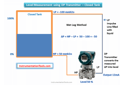
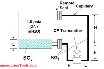
Closed Tank Level Measurement with wet leg and Transmitter installed below Tapping Point
Level Measurement with Wet leg and Installed Below Tapping Point
This calculation used for closed tank level measurement with wet leg type calibration

The formulas for calculating transmitter URV and LRV are as follows:

HP Side or LRV or Transmitter 0% = X.S1 – Y.S2

LP Side or URV or Transmitter 100% = S1(X+H) – Y.S2

Where

S1 = Specific gravity of tank liquid or process liquid.
S2 = Specific gravity of wet leg
H = Tank Height
X = Distance between transmitter and HP tapping point.
Y = Wet Leg Height

NOTE:

1. The Parameters H,X can be entered in any units like mmh20, inh20 but must be same

2. If wet leg Y is filled with same process liquid in the tank then S2=S1.

3. If wet leg Y is filled with different liquid (other than tank process liquid) then enter specific gravity of wet leg liquid in S2.

Don't Miss Our Updates
Be the first to get exclusive content straight to your email.
We promise not to spam you. You can unsubscribe at any time.
Invalid email address
You've successfully subscribed !
Contact Type Guided Wave Radar Level Transmitter Working Principle
Zero Suppression and Zero Elevation Calculations
What is Dip Tape Level Measurement?
Stilling Wells for Level Measurement
ElectroMechanical Level Measurement Working Principle
Share This Article
Facebook Whatsapp Whatsapp LinkedIn Copy Link
Share
20 Comments
  • Anonymous says:
    April 18, 2015 at 6:46 am

    Nice tool Mr.Bharadwaj.

    Really helped me.Please share more tools.

    Reply
  • Micheal Tram says:
    April 20, 2015 at 4:59 am

    Instrumentation made easy……Now Level Transmitter wet leg calibration/configuration is equal to a simple PT or TT configurastion

    Reply
  • Anonymous says:
    May 13, 2015 at 10:58 pm

    This is a very helpful tool. So much easier than having to do the calculations manually. Please don't take this link down. Thank you.

    Reply
    • S Bharadwaj Reddy says:
      May 14, 2015 at 9:55 am

      Hi,
      Thanks for the comment. These all instrumentation tools available all the time.
      Thank you,
      S Bharadwaj reddy

      Reply
      • Sathish says:
        September 25, 2015 at 9:58 am

        Really very usefull ,,thanks to Reddy,,,

        Reply
      • Zahid says:
        March 31, 2016 at 11:50 am

        I’m confused about culculation because I thinking in suppression
        X.s1 + y.s2= lrv
        But you used minus that why I confused
        Maybe I’m wrong please send me details of proper culculation and reson. Thanks

        Reply
  • muhammad sadiq says:
    October 12, 2015 at 11:19 am

    Wonderfull very usefull for instrumentation

    Reply
  • aji says:
    January 7, 2016 at 11:41 am

    how to measure level steam drum use dp transmitter

    Reply
  • manoj says:
    February 16, 2016 at 4:00 pm

    Dear sir,
    In what case Dpt transmitter range need to be in -ve say -1000mmwc to0
    1.if tank is closed and have vapour or steam in upper side and cond.pot is installed or every close tank needs cpot and _ve range steam doesent matter?
    2.if tank is open can I take o to 1000mmwc
    Both have CTo c dist. 1000mm density 1.0
    Pl.suggest.

    Reply
    • S Bharadwaj Reddy says:
      February 16, 2016 at 4:15 pm

      Hello,

      When you do the LRV & URV calculation, lets say for Open tank & Closed tank you will get negative values also. So we need Negative mmwc range of instruments for this case.Thats it. Simple if we have negative value in either LRV or URV then we need negative mmwc range of instrument. Also Depends on Calculated URV & LRV Ranges we have to select our instrument range. Either Open tank or Closed tank if your calculated LRV & URV values are withing the instrument mmwc range then we can use the instrument. Remember Negative mmwc also considered.

      Reply
      • arshad says:
        September 19, 2016 at 3:45 pm

        hi sir
        LT installed at Dearator tank is showing high alarm while actually tank level is low?? what must be the reason.??

        regards, Arshad

        Reply
  • manoj says:
    February 16, 2016 at 4:25 pm

    with ref to your answer how can be open tank have -ve mmwc at hp side since tank is at atmosephric pressure . Also talk more about condensing pot we use it only for high temp. steam vapour so if we fill pot side that is lp side to maintain head and close tank then only its -ve mmwc and if close tank , correct me if i am wrong .

    Reply
    • S Bharadwaj Reddy says:
      February 16, 2016 at 4:40 pm

      Hello Manoj, Actually it depends on how your field instrument mounted in the field. Say For open tank case if the field Tx mounted above the HP tapping point and then we can get Negative mmwc range also. Its mainly depends on Tx installation also. As Open/Closed Tank Calculations also considered. Pl Click Here For Example.

      Reply
  • Chetan Dileep Singh says:
    September 27, 2016 at 5:19 pm

    Sir is there any case when height ‘y’ and h+x will be equal?

    Reply
    • S Bharadwaj Reddy says:
      September 27, 2016 at 6:12 pm

      of course it’s possible.

      Reply
  • Mark says:
    May 26, 2017 at 11:20 am

    Great tools and examples, thanks for all your sharing!!

    I have a remote diaphragm coupled DP Tx, but the Tx is mounted at the mid-level of the tank, so NOT below or level with the bottom flange connection.

    How do i apply this to the formula, i was entering “X” as a negative value, but this isn’t giving me good results 🙁

    Reply
    • S Bharadwaj Reddy says:
      May 26, 2017 at 4:02 pm

      Hi,

      Please check these : Article 1 (click here) and Article 2 (click here), these may help you.

      Reply
  • quy says:
    June 25, 2017 at 1:05 pm

    thats so great. thanks for your post!!
    and plss. i have a closed tank wet leg with H = 103in, X = 100in, Y = 203in,
    i have been calculated URV = 0kpa and LRV = – 27.56kpa. but why in datasheet they maked thats +4.8 to +31.3 thanks you.

    Reply
  • jadav chirag says:
    April 2, 2018 at 3:38 pm

    Sir, first of all thank u for this wonderful site.
    Q.: where should we use dry leg and where to wet leg I mean application wise.

    Reply
  • jadav chirag says:
    April 2, 2018 at 3:58 pm

    Q-2: can u plz give me some idea about when should we install DP Tx 1)below HP, 2) Parallel to HP and 3) above HP? (with some industrial example)

    Reply

Leave a Reply Cancel reply

Your email address will not be published. Required fields are marked *

Stay Connected

128.3kFollowersLike
69.1kFollowersFollow
208kSubscribersSubscribe
38kFollowersFollow

Categories

Recent Comments

  • Kamli on Top Free PLC Software
  • Guifty Shimica on Top Non-PLC Certification Courses for Automation Professionals
  • Guifty Shimica on Top Non-PLC Certification Courses for Automation Professionals
  • MIHARITSOA Aina Sitraka on Top Non-PLC Certification Courses for Automation Professionals

Related Articles

Level Transmitters Auto Calibration

DP Level Transmitter Auto Calibration

Wet Leg Level Transmitter

Basics of DP Level Measurement

Which instrument is at fault in this system

Which Instrument is at Fault in this System?

Wire Guided Float Detectors

Inductively Coupled Wire Guided Float Detectors

Applications of Tilting Level Switch

How Tilt Level Switch Works ?

Closed Tank - Dry Reference Leg

Basics of Level Measurement

Sounding Level Transmitter Working Animation

FMCW radar principle

TDR & FMCW Radar Level Transmitters Principle

More Articles

Difference Between Microcontroller and Microprocessor

Difference Between Microcontroller and Microprocessor

Digital Electronics Multiple Choice Questions

Random Access Memory Objective Questions – Part 1

Surge Protection for the Fieldbus System

Vibration Probe Field Setting Procedure

Vibration Probe Field Setting Procedure

Industrial safety Objective Questions and Answers

Top 10 Industrial safety Objective Questions

Grounding Components

Selection of Components Used In Electrical Earthing or Grounding

Electrical Machines Questions and Answers

Electrical Machines Torque Production Quiz

on off valve actuator

How to Select an Actuator for Valve

Follow US
All rights reserved. Reproduction in whole or in part without written permission is prohibited.
Welcome Back!

Sign in to your account

Username or Email Address
Password

Lost your password?