Inst ToolsInst ToolsInst Tools
  • Courses
  • Automation
    • PLC
    • Control System
    • Safety System
    • Communication
    • Fire & Gas System
  • Instrumentation
    • Design
    • Pressure
    • Temperature
    • Flow
    • Level
    • Vibration
    • Analyzer
    • Control Valve
    • Switch
    • Calibration
    • Erection & Commissioning
  • Interview
    • Instrumentation
    • Electrical
    • Electronics
    • Practical
  • Q&A
    • Instrumentation
    • Control System
    • Electrical
    • Electronics
    • Analog Electronics
    • Digital Electronics
    • Power Electronics
    • Microprocessor
  • Request
Search
  • Books
  • Software
  • Projects
  • Process
  • Tools
  • Basics
  • Formula
  • Power Plant
  • Root Cause Analysis
  • Electrical Basics
  • Animation
  • Standards
  • 4-20 mA Course
  • Siemens PLC Course
Reading: Circuit Breaker Control Circuit
Share
Notification Show More
Font ResizerAa
Inst ToolsInst Tools
Font ResizerAa
  • Courses
  • Design
  • PLC
  • Interview
  • Control System
Search
  • Courses
  • Automation
    • PLC
    • Control System
    • Safety System
    • Communication
    • Fire & Gas System
  • Instrumentation
    • Design
    • Pressure
    • Temperature
    • Flow
    • Level
    • Vibration
    • Analyzer
    • Control Valve
    • Switch
    • Calibration
    • Erection & Commissioning
  • Interview
    • Instrumentation
    • Electrical
    • Electronics
    • Practical
  • Q&A
    • Instrumentation
    • Control System
    • Electrical
    • Electronics
    • Analog Electronics
    • Digital Electronics
    • Power Electronics
    • Microprocessor
  • Request
Follow US
All rights reserved. Reproduction in whole or in part without written permission is prohibited.
Inst Tools > Blog > Electrical Theory > Circuit Breaker Control Circuit

Circuit Breaker Control Circuit

Last updated: August 20, 2018 10:45 am
Editorial Staff
Electrical Theory
No Comments
Share
3 Min Read
SHARE

As we have discussed, circuit breakers may be remotely operated. In order to operate the breakers from a remote location, there must be an electrical control circuit incorporated.

The below Figure shows a simple control circuit for a remotely-operated breaker.

Control power is supplied by an AC source and then rectified to DC. The major components of a simple control circuit are: the rectifier unit, the closing relay, the closing coil, the tripping coil, the auxiliary contacts, and the circuit breaker control switch.

Circuit Breaker Control Circuit

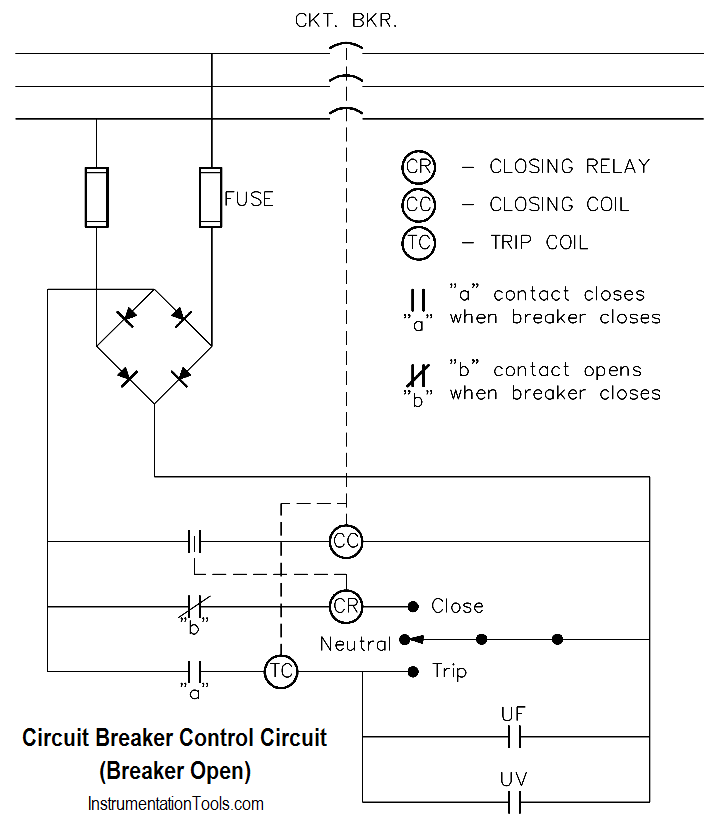
Figure : Simple Circuit Breaker Control Circuit – Breaker Open

To close the remotely-operated circuit breaker, turn the circuit breaker control switch to the close position. This provides a complete path through the closing relay (CR) and energizes the closing relay. The closing relay shuts an auxiliary contact, which energizes the closing coil (CC), which, in turn, shuts the circuit breaker, as shown in below Figure.

The breaker latches in the closed position. Once the breaker is shut, the “b” contact associated with the closing relay opens, de-energizing the closing relay and, thereby, the closing coil. When the breaker closes, the “a” contact also closes, which enables the trip circuit for manual or automatic trips of the breaker. The circuit breaker control switch may now be released and will automatically return to the neutral position.

To open the circuit breaker, turn the circuit breaker control switch to the trip position. This action energizes the trip coil (TC), which acts directly on the circuit breaker to release the latching mechanism that holds the circuit breaker closed.

When the latching mechanism is released, the circuit breaker will open, opening the “a” contact for the tripping coil and de-energizing the tripping coil. Also, when the circuit breaker opens, the “b” contact will close, thereby setting up the circuit breaker to be remotely closed using the closing relay, when desired. The circuit breaker control switch may now be released.

Circuit Breaker Control Circuit Wiring

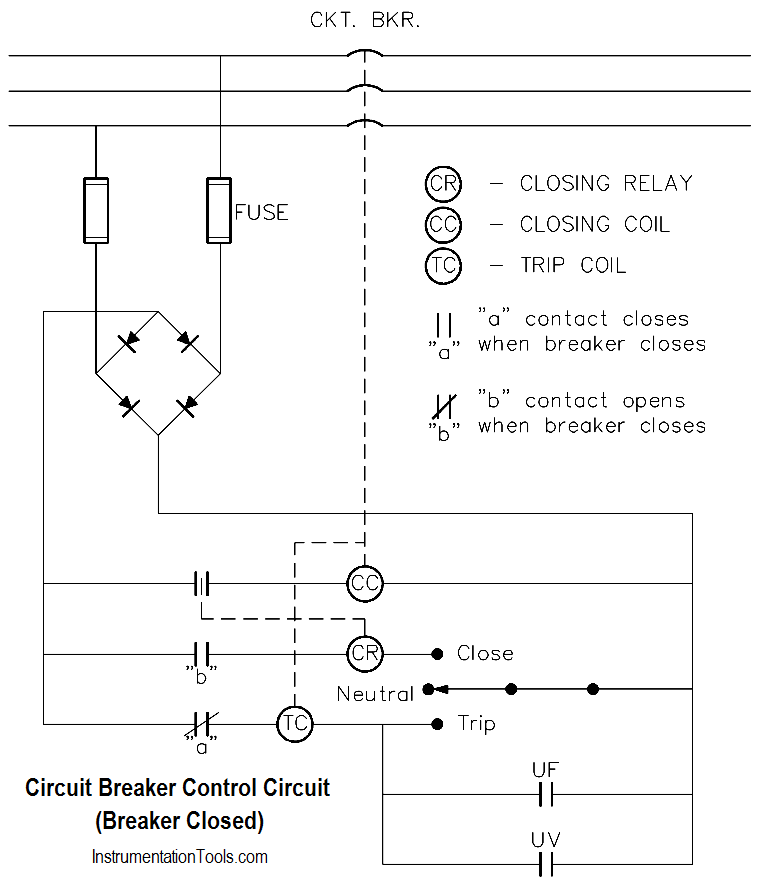
Figure : Simple Circuit Breaker Control Circuit – Breaker Closed

As you can see from above two Figures, the circuit breaker control circuit can be designed so that any one of a number of protective features may be incorporated. The three most commonly-used automatic trip features for a circuit breaker are overcurrent, underfrequency, and undervoltage. If any one of the conditions exists while the circuit breaker is closed, it will close its associated contact and energize the tripping coil, which, in turn, will trip the circuit breaker.

Don't Miss Our Updates
Be the first to get exclusive content straight to your email.
We promise not to spam you. You can unsubscribe at any time.
Invalid email address
You've successfully subscribed !

Continue Reading

Voltage Divider
DC Generator Internal Losses
Types of AC Generators
DC Machines Terminology
Transformer Impedance Ratio
Induction Motor Torque Versus Slip
Share This Article
Facebook Whatsapp Whatsapp LinkedIn Copy Link
Share
Leave a Comment

Leave a Reply Cancel reply

Your email address will not be published. Required fields are marked *

Stay Connected

128.3kFollowersLike
69.1kFollowersFollow
210kSubscribersSubscribe
38kFollowersFollow

Categories

Explore More

DC Generator Theory
Y and Delta Resistor Network Calculations
Full-Wave Rectifier Circuit
Power Factor Meter Principle
Shunt-Wound DC Generators
Three Phase AC Generators
Power in Balanced 3 Phase Loads
Block Diagram

Keep Learning

Compounded DC Generator

Parallel AC Generators

DC Circuit Node Equations

DC Circuit Analysis Node Equations

Basic AC Generator

AC Generator Parts

Transformer Operation Under No-Load

Transformer Operation Under No-Load

Half-Wave Rectifier Circuit

Half-Wave Rectifier Circuit

Potential Difference Across a Conductor Causes a Current to Flow

Conductor, Insulator, Resistor and Current Flow

DC Machine

DC Machines Construction

Inductive Time Constant

Inductive Time Constant

Learn More

Differential Pressure versus Flow Rate

Orifice Flowmeter Rangeability

Difference between Globe Valve and Gate Valve

Difference between Globe Valve and Gate Valve ?

Float Level Measurement

Types of Level Measurement

Electrical & Instrumentation QA QC Interview Questions

100 Electrical & Instrumentation QA QC Interview Questions

Steam Letdown Station Problems

Steam Letdown Station Problems and their Solutions

Leading Power Factor

Power Factor

Linear to Square Root Extraction

Functions of Pressure Detectors

Functions of Pressure Detectors

Menu

  • About
  • Privacy Policy
  • Copyright

Quick Links

  • Learn PLC
  • Helping Hand
  • Part Time Job

YouTube Subscribe

Follow US
All rights reserved. Reproduction in whole or in part without written permission is prohibited.
Welcome Back!

Sign in to your account

Username or Email Address
Password

Lost your password?