The shielding in the cables of Instrumentation and Control systems is intended to block electrical noise (interference) induced by the effects of electric fields in the environment.
Electrical noise or interference are all unwanted signals of electrical origin that can alter the original signal. It is either by coupling inductive or electrostatic discharge.
Most applications of the cables for Instrumentation are the process-oriented acquisition of very low power signals, therefore it is necessary to block as much as possible interference or external noise that may distort information.
Consider the following while selecting shielding:
Cables with a few types of screens by the manufacturers are discussed below.
The copper tape type screen consists of a tape of copper applied in a helical manner, to which has added a series of copper wires.
The purpose of this type of configuration is to make the shielding resistance very small, which is equivalent to a higher current carrying capacity in the event of a fault.
Protection against induction coupling (coupling magnetic by indentations of the screen) in high frequencies and electrostatic discharges.
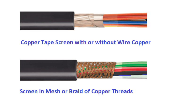
The screen type mesh, are copper wires twisted together, applied on the core or filling of the cable forming an electrostatic fabric.
This type of shielding provides great flexibility to the cable and protection against coupling by induction or diffusion (usually caused by screen resistance at low frequencies) where low DC resistance is required.
In automation systems, proper grounding plays an important role in the health and integrity of the overall process signals.
Proper grounding protects automation systems from possible damage due to
Apart from the above, a proper grounding hierarchy helps reduce signal noise and interference.
It is by providing a low-resistance pathway for these unwanted voltages and currents that could lead to safety hazards or degradation of processing control signals. In looking into the field of problems associated with signal noise, erratic spikes, or interference problems, we find that most of these problems arise from poor grounding.
To ensure proper grounding of instrumentation systems, a clear grounding scheme must be followed.
One must carefully evaluate the whole grounding system when diagnosing a problem or when designing new plants. These areas are grounding in the field, interconnecting wiring, and grounding within the control buildings or the central process interface.
In the field, the enclosures of all instrument devices have to connect to the ground, usually the general grounding network of the plant, or a link to an electrically conductive structure that is connected to the network.
Raceways such as ducts and trays are grounded at both ends.
One must properly cut the tape and shield and its ground wire in the field, near the instrument. From field instruments, all the way to sorting cabinets, shield drain wires must be treated and terminated similar to signal cables.
Once the instrument loop reaches the marshaling cabinet, the shield drain wires have to be assembled and tied together and terminate at the bus bar for the ground shield.
Exposed parts of discharge cables within junction boxes or sorting cabinets should be covered with insulation tape to protect against the possibility of multiple drain wires contacting each other.
In addition to the above measure, all spare pairs or triads that run between field junction boxes and sorting cabinets must be terminated at both ends.
In some cases, it would be helpful to ground the replacement wiring in the classification cabinets to minimize the potential noise pickup.
In the control room or the process interface of buildings, the cabinets of the process automation system and classification cabinets must be equipped with two bars: one for bus AC & DC ground connection and another for common discharge cables and shield.
The DC bus bar and shield ground must be electrically isolated from the cabinet structure.
All shield drain cables and DC cables must be joined and connected to the insulated bus bars. It is vitally important to secure screened discharge cables to the ground at one end, usually in marshaling classification cabinets. Grounding them at both ends can result from in-ground loops, which happen to be a major cause of signal noise.
Learn the example of flip-flop PLC program for lamps application using the ladder logic to…
In this article, you will learn the STAR DELTA programming using PLC controller to start…
Lube oil consoles of rotary equipment packages in industrial process plants are usually equipped with…
Rotating equipment packages such as pumps, compressors, turbines need the lube oil consoles for their…
This article explains how to blink lights in ladder logic with a detailed explanation video…
In this article, a simple example will teach you the conversion from Boolean algebra to…


View Comments
Made easy to understand,nice article.