Inst ToolsInst ToolsInst Tools
  • Courses
  • Automation
    • PLC
    • Control System
    • Safety System
    • Communication
    • Fire & Gas System
  • Instrumentation
    • Design
    • Pressure
    • Temperature
    • Flow
    • Level
    • Vibration
    • Analyzer
    • Control Valve
    • Switch
    • Calibration
    • Erection & Commissioning
  • Interview
    • Instrumentation
    • Electrical
    • Electronics
    • Practical
  • Q&A
    • Instrumentation
    • Control System
    • Electrical
    • Electronics
    • Analog Electronics
    • Digital Electronics
    • Power Electronics
    • Microprocessor
  • Request
Search
  • Books
  • Software
  • Projects
  • Process
  • Tools
  • Basics
  • Formula
  • Power Plant
  • Root Cause Analysis
  • Electrical Basics
  • Animation
  • Standards
  • 4-20 mA Course
  • Siemens PLC Course
Reading: Bubbler Level Measurement Animation
Share
Font ResizerAa
Inst ToolsInst Tools
Font ResizerAa
  • Courses
  • Design
  • PLC
  • Interview
  • Control System
Search
  • Courses
  • Automation
    • PLC
    • Control System
    • Safety System
    • Communication
    • Fire & Gas System
  • Instrumentation
    • Design
    • Pressure
    • Temperature
    • Flow
    • Level
    • Vibration
    • Analyzer
    • Control Valve
    • Switch
    • Calibration
    • Erection & Commissioning
  • Interview
    • Instrumentation
    • Electrical
    • Electronics
    • Practical
  • Q&A
    • Instrumentation
    • Control System
    • Electrical
    • Electronics
    • Analog Electronics
    • Digital Electronics
    • Power Electronics
    • Microprocessor
  • Request
Follow US
All rights reserved. Reproduction in whole or in part without written permission is prohibited.
Inst Tools > Blog > Animation > Bubbler Level Measurement Animation

Bubbler Level Measurement Animation

Last updated: September 28, 2018 11:56 am
Editorial Staff
Animation How It Works Level Measurement
8 Comments
Share
1 Min Read
SHARE

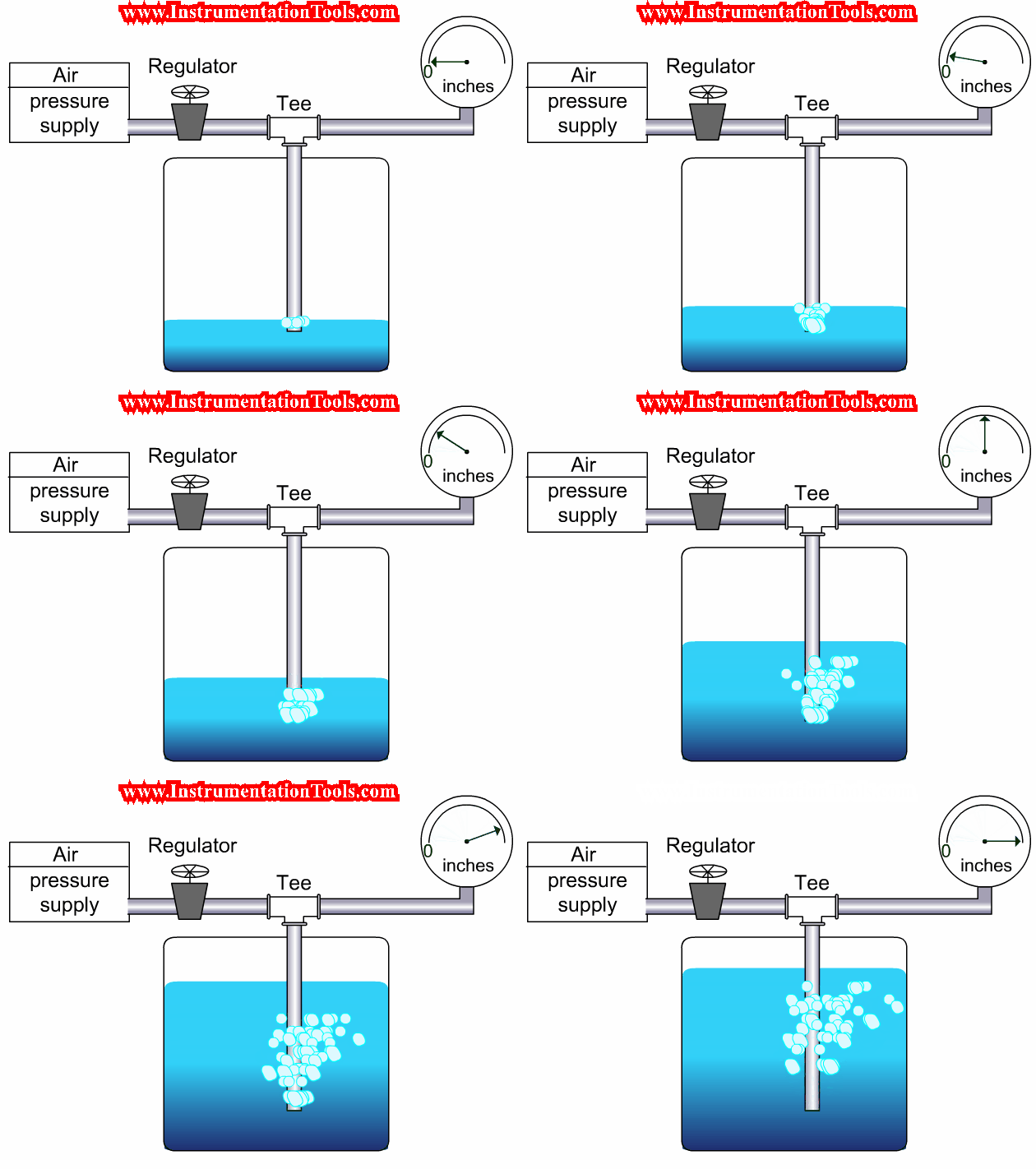
Bubbler Level Measurement Animation shows the working principle of bubbler level sensor.

Working Principle:

A fixed constant air supply will be given at the inlet (min 10psi). When there is no level in the tank then total air passed to atmosphere through pipe in the tank. When the level in tank increases means the proportional back pressure increases and the increased back pressure is proportional to level in tank.

When tank level is more then back pressure will increases. With the use a electronic transmitters (like pressure transmitters) we can convert the back pressure signal into 4-20mA level signal.
Bubbler Level Measurement Animation

Don't Miss Our Updates
Be the first to get exclusive content straight to your email.
We promise not to spam you. You can unsubscribe at any time.
Invalid email address
You've successfully subscribed !

Continue Reading

Scintillation Counter Principle
What is Displacer Level Sensor ?
Bubbler Level Sensor
Capacitance Level Transmitter Animation
Eddy Current Working Principle Animation
Difference between Transparent Level Gauge and Reflex Level Gauge
Share This Article
Facebook Whatsapp Whatsapp LinkedIn Copy Link
Share
8 Comments
  • Dinesh Kumar C says:
    September 25, 2015 at 10:46 am

    Hi Bharadwaj,

    All the contents are really good and helps to refresh the principles. Additionally can you also add the applications and usage of specific measurements in field. Just an idea.

    Eg: Magnetic Flow meters, Can be used only in Conductive fluids.

    Reply
    • S Bharadwaj Reddy says:
      September 25, 2015 at 2:27 pm

      Sure, i will do my best. Also if any one interested to share their knowledge/data, plz send the information to [email protected]
      Thanks

      Reply
      • pavan says:
        May 9, 2016 at 2:37 am

        Sir, Parallely keep on posting related to PLC, DCS, MODBUS COMMUNICATION etc.

        Reply
    • Aamir Ahmad says:
      October 15, 2021 at 7:18 pm

      why are using Dp transmitter

      Reply
  • ajaz sheikh says:
    May 9, 2016 at 3:05 pm

    Plz can any one tell how to calibrate LL pressure switch and HH pressure switch

    Reply
  • aarshav says:
    June 12, 2016 at 6:49 am

    awesome!! thanks for introducing the basics..
    so kind of you

    Reply
  • Sushil Gharat says:
    November 22, 2016 at 1:50 am

    Great knowledge sharing..
    Much needed..
    Thank you very much..

    Reply
  • nore says:
    September 12, 2021 at 4:40 pm

    Hello,

    We have a wastewater pond, we installed two different level transmitters, guided wave radar, and bubble type radar, the depth of the pond is 3.8 Mtrs, but both transmitters are giving different readings, radar showing 57% while bubble showing 48% reading, is the working principle different for both transmitters? for example the bubble measure from the bottom while the radar reflects from the top of wastewater?

    Reply

Leave a Reply Cancel reply

Your email address will not be published. Required fields are marked *

Stay Connected

128.3kFollowersLike
69.1kFollowersFollow
210kSubscribersSubscribe
38kFollowersFollow

Categories

Explore More

In-Line Flow Switch Working Principle and Animation
Effects of Symmetric and Asymmetric Capillary Tube Pressure Measurement
What is Thermal Differential Level Measurement?
Limit Switch Animation
Surface Detector Level Gauges (Plumb-bob)
Displacer Level Transmitter Dry Calibration with Weights
Radar and Ultrasonic Level Transmitter Practical Problems Troubleshooting
Types of Industrial Level Sensors

Keep Learning

ROTARY ABUTMENT FLOW METERS WORKING ANIMATION

Rotary Abutment Flow Meters Working Principle and Animation

Capacitive Level Switch Principle

Capacitive Level Switch Principle

Bubbler Liquid Level Transmitter Calculation

Bubbler Liquid Level Transmitter Calculation

Variable Area Flow Meters

Variable Area Flow Meters – Principle, Advantages, Disadvantages

Displacer Level Transmitter Intrenal Diagram

Displacer Level Transmitter Working Principle

Closed Tank Level Measurement using DP Transmitter

How can we use a DP Flow Transmitter for Level Measurement

torque tube displacement level transmitter

Level Troll working principle

Level Instruments

Level Instruments General Specifications

Learn More

Head Mount Temperature Transmitter

What is a Head Mount Temperature Transmitter? – Advantages

Ziegler-Nichols closed-loop Formula

Tuning a Temperature Process Control Loop

Relay Wiring

Animation of Electromagnetic Relay

Solenoid

Difference between AC and DC Solenoid Valves

Sampling Circuits Objective Questions

Sampling Circuits Objective Questions

PLC Program three-phase electric motor

Identify the Problem in the PLC Program

Power Systems Questions & Answers

Power Systems MCQ Series 15

Turbo-Compressor Problem

Turbo-Compressor Problem – Root Cause Analysis

Menu

  • About
  • Privacy Policy
  • Copyright

Quick Links

  • Learn PLC
  • Helping Hand
  • Part Time Job

YouTube Subscribe

Follow US
All rights reserved. Reproduction in whole or in part without written permission is prohibited.
Welcome Back!

Sign in to your account

Username or Email Address
Password

Lost your password?