Inst ToolsInst ToolsInst Tools
  • Courses
  • Automation
    • PLC
    • Control System
    • Safety System
    • Communication
    • Fire & Gas System
  • Instrumentation
    • Design
    • Pressure
    • Temperature
    • Flow
    • Level
    • Vibration
    • Analyzer
    • Control Valve
    • Switch
    • Calibration
    • Erection & Commissioning
  • Interview
    • Instrumentation
    • Electrical
    • Electronics
    • Practical
  • Q&A
    • Instrumentation
    • Control System
    • Electrical
    • Electronics
    • Analog Electronics
    • Digital Electronics
    • Power Electronics
    • Microprocessor
  • Request
Search
  • Books
  • Software
  • Projects
  • Process
  • Tools
  • Basics
  • Formula
  • Power Plant
  • Root Cause Analysis
  • Electrical Basics
  • Animation
  • Standards
  • 4-20 mA Course
  • Siemens PLC Course
Reading: Baffle Nozzle Question
Share
Font ResizerAa
Inst ToolsInst Tools
Font ResizerAa
  • Courses
  • Design
  • PLC
  • Interview
  • Control System
Search
  • Courses
  • Automation
    • PLC
    • Control System
    • Safety System
    • Communication
    • Fire & Gas System
  • Instrumentation
    • Design
    • Pressure
    • Temperature
    • Flow
    • Level
    • Vibration
    • Analyzer
    • Control Valve
    • Switch
    • Calibration
    • Erection & Commissioning
  • Interview
    • Instrumentation
    • Electrical
    • Electronics
    • Practical
  • Q&A
    • Instrumentation
    • Control System
    • Electrical
    • Electronics
    • Analog Electronics
    • Digital Electronics
    • Power Electronics
    • Microprocessor
  • Request
Follow US
All rights reserved. Reproduction in whole or in part without written permission is prohibited.
Inst Tools > Blog > Practical Questions > Baffle Nozzle Question

Baffle Nozzle Question

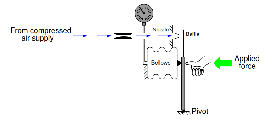
In the following baffle nozzle system, the nozzle pressure is allowed to react against any external force by generating a force with a bellows unit, to push the baffle away from the nozzle.

Last updated: September 12, 2020 7:54 pm
Editorial Staff
Practical Questions
No Comments
Share
3 Min Read
SHARE

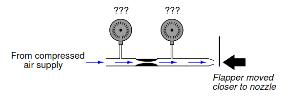
In the following baffle/nozzle system, the nozzle pressure is allowed to react against any external force by generating a force with a bellows unit, to push the baffle away from the nozzle.

The particular bellows in this mechanism are designed to be “slack,” having little spring effect to self-restrain its motion. Whatever force generated by the pressure acting against the bellows’ surface area gets directly transferred to the lever:

Baffle Nozzle

What will happen in this system if someone pushes the lever toward the nozzle with their thumb? Explain every step in your reasoning – don’t just describe a final result!

Now, suppose we modify this system to have a bellows with a larger diameter:

Flapper Nozzle

What will happen in this system if someone pushes the lever toward the nozzle with the same amount of force as before (with the smaller bellows)? How will this system respond to the same stimulus? Again, explain every step in your reasoning – don’t just describe a final result!

What will happen in this system if we were to take the original (smaller) bellows mechanism and push on it with the same force but at a position closer to the pivot point than the bellows? As usual, explain every step in your reasoning:

Baffle Nozzle Question

1. Explain, in simple terms, what effect bellows size has on the gain of the system, and why.

2. Suppose the compressed air supply pressure was 10 PSI in both cases. If this supply pressure were to drop to a lower value such as 8 PSI, what effect (if any) would this have on the gauge pressure in each scenario as the system responds to the same amount of applied force? Why or why not?

3. Determine whether or not the output pressure would rise to the same level with force applied to the lever if the air supply was cut off (and the supply tube plugged so that air could not leak out).

4. A common misconception among students first analyzing these mechanisms is that the output pressure is being generated by the bellows: that is to say, that the action of collapsing the bellows by the force of the hand is what makes the air inside become compressed. Explain why this is a misconception, and further explain how and why the resulting pressure arises.

Share your answers with us through the below comments section.

Read Next:

  • Bellows Pressure Sensor
  • Baffle Nozzle Assembly
  • Pressure Regulator Principle
  • Pneumatic Transmitter
  • Instrument Mechanic Interview

Credits: Tony R. Kuphaldt
Don't Miss Our Updates
Be the first to get exclusive content straight to your email.
We promise not to spam you. You can unsubscribe at any time.
Invalid email address
You've successfully subscribed !

Continue Reading

Process Control Loop Testing
Electronic Force Balance Pressure Transmitter
Questions on Pneumatic Transmitter and Repeater
Determine LRV and URV settings for the Level Transmitter
Practical Process Control System Questions & Answers – 8
Flapper Nozzle Questions
Share This Article
Facebook Whatsapp Whatsapp LinkedIn Copy Link
Share
Leave a Comment

Leave a Reply Cancel reply

Your email address will not be published. Required fields are marked *

Stay Connected

128.3kFollowersLike
69.1kFollowersFollow
210kSubscribersSubscribe
38kFollowersFollow

Categories

Explore More

Practical Process Control System Questions & Answers – 3
Double Block and Bleed Valves Opening or Closing Sequence
Electric-driven Air Compressor Troubleshooting
Air Pressure Inside the Tank
PLC Practice Questions
Explain What these Spool Valve Symbols Represent?
Determine Effect of Each Fault for Pneumatic Force-balance System
Float-type Level Switch to Control a pump

Keep Learning

liquid flow control loop

Liquid Flow Control Loop Controller Action

PLC Program three-phase electric motor

Identify the Problem in the PLC Program

Simple High Level Indicator Circuit

Simple High Level Indicator Circuit

Differential Capacitance Pressure Sensor Circuit

Differential Capacitance Pressure Sensor Circuit

Stilling well in liquid level measurement

Stilling Well in Interface Level Measurement System

Baffle Nozzle Assembly Sensitive Mechanism

Baffle Nozzle Assembly Sensitive Mechanism

Identify the Pressure Gauge Error

Identify the Pressure Gauge Error

PLC Program for Valves

PLC Pump Permissive Interlocks

Learn More

Cable screen shall not be grounded

Cable Screen shall not be Grounded at Field Device ?

Serial Communication Interview Questions

Serial Communication Interview Questions and Answers

PLC Subroutine

Allen Bradley PLC Subroutines

Basics of Electricity Rates

Basics of Electricity Rates

PLC PID tuning parameters

Programming and Tuning PID Controller in PLC – Siemens TIA Portal

Instrumentation Android App

Perfume filling system PLC program

CX Programmer Example: Perfume Mixing and Filling System

Cell Constant in Conductivity Analyzer

What is Cell Constant in Conductivity Analyzer? and its Importance

Menu

  • About
  • Privacy Policy
  • Copyright

Quick Links

  • Learn PLC
  • Helping Hand
  • Part Time Job

YouTube Subscribe

Follow US
All rights reserved. Reproduction in whole or in part without written permission is prohibited.
Welcome Back!

Sign in to your account

Username or Email Address
Password

Lost your password?