Inst ToolsInst ToolsInst Tools
  • Courses
  • Automation
    • PLC
    • Control System
    • Safety System
    • Communication
    • Fire & Gas System
  • Instrumentation
    • Design
    • Pressure
    • Temperature
    • Flow
    • Level
    • Vibration
    • Analyzer
    • Control Valve
    • Switch
    • Calibration
    • Erection & Commissioning
  • Interview
    • Instrumentation
    • Electrical
    • Electronics
    • Practical
  • Q&A
    • Instrumentation
    • Control System
    • Electrical
    • Electronics
    • Analog Electronics
    • Digital Electronics
    • Power Electronics
    • Microprocessor
  • Request
Search
  • Books
  • Software
  • Projects
  • Process
  • Tools
  • Basics
  • Formula
  • Power Plant
  • Root Cause Analysis
  • Electrical Basics
  • Animation
  • Standards
  • 4-20 mA Course
  • Siemens PLC Course
Reading: Baffle Nozzle Question
Share
Font ResizerAa
Inst ToolsInst Tools
Font ResizerAa
  • Courses
  • Design
  • PLC
  • Interview
  • Control System
Search
  • Courses
  • Automation
    • PLC
    • Control System
    • Safety System
    • Communication
    • Fire & Gas System
  • Instrumentation
    • Design
    • Pressure
    • Temperature
    • Flow
    • Level
    • Vibration
    • Analyzer
    • Control Valve
    • Switch
    • Calibration
    • Erection & Commissioning
  • Interview
    • Instrumentation
    • Electrical
    • Electronics
    • Practical
  • Q&A
    • Instrumentation
    • Control System
    • Electrical
    • Electronics
    • Analog Electronics
    • Digital Electronics
    • Power Electronics
    • Microprocessor
  • Request
Follow US
All rights reserved. Reproduction in whole or in part without written permission is prohibited.
Inst Tools > Blog > Practical Questions > Baffle Nozzle Question

Baffle Nozzle Question

In the following baffle nozzle system, the nozzle pressure is allowed to react against any external force by generating a force with a bellows unit, to push the baffle away from the nozzle.

Last updated: September 12, 2020 7:54 pm
Editorial Staff
Practical Questions
No Comments
Share
3 Min Read
SHARE

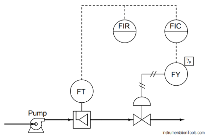
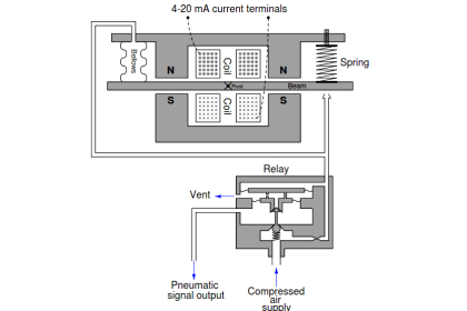
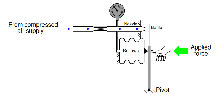
In the following baffle/nozzle system, the nozzle pressure is allowed to react against any external force by generating a force with a bellows unit, to push the baffle away from the nozzle.

The particular bellows in this mechanism are designed to be “slack,” having little spring effect to self-restrain its motion. Whatever force generated by the pressure acting against the bellows’ surface area gets directly transferred to the lever:

Baffle Nozzle

What will happen in this system if someone pushes the lever toward the nozzle with their thumb? Explain every step in your reasoning – don’t just describe a final result!

Now, suppose we modify this system to have a bellows with a larger diameter:

Flapper Nozzle

What will happen in this system if someone pushes the lever toward the nozzle with the same amount of force as before (with the smaller bellows)? How will this system respond to the same stimulus? Again, explain every step in your reasoning – don’t just describe a final result!

What will happen in this system if we were to take the original (smaller) bellows mechanism and push on it with the same force but at a position closer to the pivot point than the bellows? As usual, explain every step in your reasoning:

Baffle Nozzle Question

1. Explain, in simple terms, what effect bellows size has on the gain of the system, and why.

2. Suppose the compressed air supply pressure was 10 PSI in both cases. If this supply pressure were to drop to a lower value such as 8 PSI, what effect (if any) would this have on the gauge pressure in each scenario as the system responds to the same amount of applied force? Why or why not?

3. Determine whether or not the output pressure would rise to the same level with force applied to the lever if the air supply was cut off (and the supply tube plugged so that air could not leak out).

4. A common misconception among students first analyzing these mechanisms is that the output pressure is being generated by the bellows: that is to say, that the action of collapsing the bellows by the force of the hand is what makes the air inside become compressed. Explain why this is a misconception, and further explain how and why the resulting pressure arises.

Share your answers with us through the below comments section.

Read Next:

  • Bellows Pressure Sensor
  • Baffle Nozzle Assembly
  • Pressure Regulator Principle
  • Pneumatic Transmitter
  • Instrument Mechanic Interview

Credits: Tony R. Kuphaldt

Don't Miss Our Updates
Be the first to get exclusive content straight to your email.
We promise not to spam you. You can unsubscribe at any time.
Invalid email address
You've successfully subscribed !

Continue Reading

Surface-mounted Water Pump
Programmable Logic Controller (PLC) Questions and Answers – 8
Problem on Solar Hot Air Collector and Variable Speed Fan
Programmable Logic Controller (PLC) Questions and Answers – 2
Practical Process Control System Questions & Answers – 3
Pressure Transmitter using Potentiometer and Diaphragm
Share This Article
Facebook Whatsapp Whatsapp LinkedIn Copy Link
Share
Leave a Comment

Leave a Reply Cancel reply

Your email address will not be published. Required fields are marked *

Stay Connected

128.3kFollowersLike
69.1kFollowersFollow
210kSubscribersSubscribe
38kFollowersFollow

Categories

Explore More

Indentify Faults in Simple Lamp Circuit including Failed Wires
Programmable Logic Controller (PLC) Questions and Answers – 13
PLC Electric Motor Interlocks
Troubleshoot Allen Bradley PLC Logic
Galileo Thermometer
Electronic Pressure Sensor with Bourdon Tube and LVDT
Question on Remote Seal with Capillary Tubing Transmitter
How Do You Connect the Differential Pressure Gauge at the Filter?

Keep Learning

thermocouple Transmitter Formula

Calculate Process Temperature using a Thermocouple

Programmable Logic Controller (PLC) Questions and Answers

Programmable Logic Controller (PLC) Questions and Answers – 4

Calculate Temperature of Four Wire RTD

Calculate the Temperature of 4 Wire RTD

Draw the Symbols for Liquid Level Measuring Instruments

Draw the Symbols for Liquid Level Measuring Instruments

Allen-Bradley MicroLogix 1000 controller

PLC Switch Actuation Status

float-type level switch control a pump

Float-type Level Switch to Control a pump

Dual-junction thermocouple circuit

Find Thermocouple Ouput Voltage

Chemical Seal Pressure Transmitter

What is the Purpose of Chemical Seals Pressure Transmitter?

Learn More

Vortex Flow Meter Animation

Basic Working Principle of Vortex Flowmeter

Important Factors Consider during Piping Design

Important Factors Consider during Piping Design

Annunciators - 2

What is a Annunciator ?

Facts of Control Valves

Facts About Control Valves

Single-element drum level control system

Single Element Drum Level Control System

Digital Electronics Multiple Choice Questions

Transistor Transistor Logic (TTL) Objective Questions

Process Control Terms

143 Process Control Terms and Glossary – Questions Answers

SCADA Systems

SCADA Systems

Menu

  • About
  • Privacy Policy
  • Copyright

Quick Links

  • Learn PLC
  • Helping Hand
  • Part Time Job

YouTube Subscribe

Follow US
All rights reserved. Reproduction in whole or in part without written permission is prohibited.
Welcome Back!

Sign in to your account

Username or Email Address
Password

Lost your password?