What is Vibration
Vibration is static and dynamic imbalance of equipment.
Vibration is the oscillation, or moving back and forth of an object. The word vibrations consciously or unconsciously use it as a measure of how well things are running. For vibration to get start it takes some effort, either external or internal to get vibration going, some input of energy through an applied force. Once we have put energy into the system to make it vibrate, how do we characterize the vibration? Amplitude and frequency are common characteristics. When we deal with several vibration phase also will becomes important.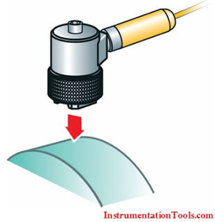
The force we apply to vibrate directly affects the vibration. The more force we apply, the greater the vibration amplitude. But what acts to limit the vibration? As we make stiffer, like a spring, the amplitude of vibration decreases.
We can say that 3 physical characteristics control the vibration.
- Mass
- Stiffness (spring)
- Damping
Vibration measurement
The principle characteristics of the vibration signal that we measure are
- Amplitude
- Frequency
- Phase
- Amplitude
Amplitude
Amplitude is a measure of how severe the vibration is and can be expressed in 3 different ways: Peak to peak, Zero to peak and RMS, depending on what signal we are measuring.
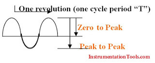
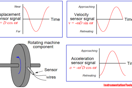
Vibration is measured either in terms of displacement, velocity or acceleration. Vibration displacement is always measured as Peak to Peak, a measure of the total excursion of the rotor or machine casing in MILS or MICROMETERS. Vibration velocity and Acceleration are measured as Zero to Peak or RMS. Units used are “inches per second” or “millimeters per second” for velocity or in terms of “G” or “meters per second per second” for acceleration.
Frequency
Frequency is a measure of how fast a body is vibrating and is used to identify the source of vibration. Normally Frequency is expressed in shaft rotative speed. If a vibration is at the same frequency as the shaft speed, this will be 1X or 1 time shaft speed. If it is twice it is 2X. Also the frequency may be expressed in cycles per second or Hertz, or in cycles per minute. The period of vibration is measured in seconds and the reciprocal calculated will give in Hertz.
Phase
Phase is a simple timing relationship between 2 events which may be 2 vibration signals for Relative Phase measurements or a vibration signal and a keyphasor reference signal for Absolute measurements. Both these are important vibration signal properties.
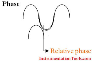
To measure the relative phase between 2 vibration signals, both signals should be at the same frequency and should be in the same units ie. Both displacements, both velocity or both acceleration. Both signals may be taken as the reference and the relative phase is expressed as an angle between Oo and 180o leading or lagging.
Shape or Form
The shape or form can be viewed by using the oscilloscope. The shape can be viewed by combining the signals from the vertical and horizontal proximity transducers. For most machines this will be either circle for uniform mechanical impedance or an ellipse with low eccentricity where the mechanical impedance is not uniform in all directions. The shape can be a good indicator of non uniform mechanical impedance, preloads such as misalignment and rotor to stator rubbing.
Reference frame for vibration measurement
Each vibration transducer measures the vibration in a different way, either a relative measurement or an absolute measurement.
Relative measurement
The proximity transducer system measures the motion of the shaft relative to the transducer tip. As the transducer is located close to the bearing (less than 6”) the proximity probe can be considered to measure the motion of the shaft relative to the bearing. This gives an indication of the amount of available clearance taken up by the shaft motion. If the transducer mounting is in motion due to vibration, this will result in an output from the transducer which will appear as if the shaft is moving.
If the shaft and the transducer mounting are moving together in phase, the resultant output from the probe will be zero as if there is no shaft vibration. Great care in mounting should be taken to ensure that this situation will not arise.
Absolute measurement
Absolute measurement or seismic measurement are made using either a velocity or acceleration transducer mounted on the bearing housing or machine casing. Absolute measurements are needed where casing or housing motion is significant. The velocity or acceleration transducer measures motion relative to free space, with the coil as reference for the velocity transducer and the mass as reference for the acceleration transducer.
Shaft absolute measurement is made by measuring the shaft relative displacement using a proximity probe and the bearing displacement using either a velocity probe or accelerometer.
The velocity or acceleration measurement are integrated (or double integrated in the case of acceleromter) and then subtracted from the shaft relative displacement.
Only in rare cases is the shaft absolute displacement required or machine measurement, shaft relative displacement usually provides sufficient information.
Position measurement
Axial Thrust position
This is a measurement of the rotor within the thrust bearing clearance. The measurement is usually made using two proximity probe mounted in the thrust bearing observing the thrust collar.
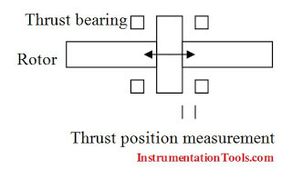
If this is not practical, the probes may be mounted at some location close to the bearing observing the shaft end or a specially fitted collar. To ensure reliable measurements, axial thrust position should always be made using 2 transducers.
The signal from the transducers are monitored using a dual voting thrust position monitor which looks at both the signals and compares them with the alarm levels. If either signal exceeds the first preset alarm value the alarm will be indicated and relay will change state. If the levels increase to the second preset level the monitor will indicate the alarm but unless both this signals exceeds this value the relay will not change its state.
Radial Position
Radial position of the shaft within the bearing clearance can be measured using the Dc signal installed from the proximity probe.
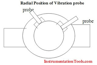
The DC signal is measured when the machine is at rest with the shaft sitting at the bottom of the bearing and again when the machine is running.
With the shaft supported on its oil film, the change in DC voltage measured can be used to calculate the new position of the shaft center line. This can be a very important measurement to determine the condition of the shaft alignment and also to indicate any bearing wear which might be occurring. The signal needed to make these measurement are available at the front panel of the monitors.
Differential measurement
For large steam turbines with long shaft systems, an additional axial position measurement may be required to measure the position of the rotor at a location away from the machine thrust bearing.
In all machines the thrust bearing is rigidly fixed to the machine foundation and the casings are free to move due to thermal expansion in an axial direction. For large machines the thermal expansion of the rotor will not be the same as the expansion of the casing. The differential expansion measurement is to measure this difference and ensure that the rotor does not touch the stationary parts.
Shaft eccentricity
This is the bow or bend in a machine shaft and is measured at very low shaft speed in the order of a few revolutions per minute.
Ideally the proximity transducer is mounted some distance away from the bearing so that the maximum deflection will be detected when the machine is run at slow roll speed. The measurement made by the transducer is then not due to dynamic motion but is a purely measure of the shaft bow.


I want more information please
At our plant we have a 72″OD x 1/2″thick carbon steel pipe fitted with a 20″ long stainless steel bellows expansion joint that has a 69.5″OD x 3/8″thick x 15″ long carbon steel cantilevered liner that is welded to the inside surface of the 72″OD pipe at one end.
Inside the expansion joint is steam at partial vacuum and it is vibrating.
We would like to measure the current orbit of the liner and try reducing vibration by installing jacking screws around the perimeter to dampen vibration.
Do you have a proximity sensor that could detect the motion of the liner?
Dave Moffat PEng
david.moffat@opg.com
905 839 1151 x 2167