Inst ToolsInst ToolsInst Tools
  • Courses
  • Automation
    • PLC
    • Control System
    • Safety System
    • Communication
    • Fire & Gas System
  • Instrumentation
    • Design
    • Pressure
    • Temperature
    • Flow
    • Level
    • Vibration
    • Analyzer
    • Control Valve
    • Switch
    • Calibration
    • Erection & Commissioning
  • Interview
    • Instrumentation
    • Electrical
    • Electronics
    • Practical
  • Q&A
    • Instrumentation
    • Control System
    • Electrical
    • Electronics
    • Analog Electronics
    • Digital Electronics
    • Power Electronics
    • Microprocessor
  • Request
Search
  • Books
  • Software
  • Projects
  • Process
  • Tools
  • Basics
  • Formula
  • Power Plant
  • Root Cause Analysis
  • Electrical Basics
  • Animation
  • Standards
  • 4-20 mA Course
  • Siemens PLC Course
Reading: Transistor Amplifier Working Principle
Share
Notification Show More
Font ResizerAa
Inst ToolsInst Tools
Font ResizerAa
  • Courses
  • Design
  • PLC
  • Interview
  • Control System
Search
  • Courses
  • Automation
    • PLC
    • Control System
    • Safety System
    • Communication
    • Fire & Gas System
  • Instrumentation
    • Design
    • Pressure
    • Temperature
    • Flow
    • Level
    • Vibration
    • Analyzer
    • Control Valve
    • Switch
    • Calibration
    • Erection & Commissioning
  • Interview
    • Instrumentation
    • Electrical
    • Electronics
    • Practical
  • Q&A
    • Instrumentation
    • Control System
    • Electrical
    • Electronics
    • Analog Electronics
    • Digital Electronics
    • Power Electronics
    • Microprocessor
  • Request
Follow US
All rights reserved. Reproduction in whole or in part without written permission is prohibited.
Inst Tools > Blog > Electronic Devices & Circuits > Transistor Amplifier Working Principle

Transistor Amplifier Working Principle

Last updated: September 27, 2016 5:11 am
Editorial Staff
Electronic Devices & Circuits
No Comments
Share
3 Min Read
SHARE

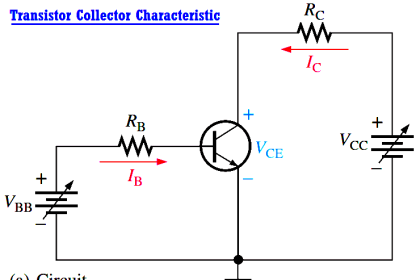
A linear amplifier provides amplification of a signal without any distortion so that the output signal is an exact amplified replica of the input signal. A voltage-divider biased transistor with a sinusoidal ac source capacitively coupled to the base through C1 and a load capacitively coupled to the collector through C2 is shown in Figure. The coupling capacitors block DC and thus prevent the internal source resistance, Rs, and the load resistance, RL, from changing the dc bias voltages at the base and collector.

The capacitors ideally appear as shorts to the signal voltage. The sinusoidal source voltage causes the base voltage to vary sinusoidally above and below its dc bias level, VBQ. The resulting variation in base current produces a larger variation in collector current because of the current gain of the transistor.

Transistor Amplifier Working Principle

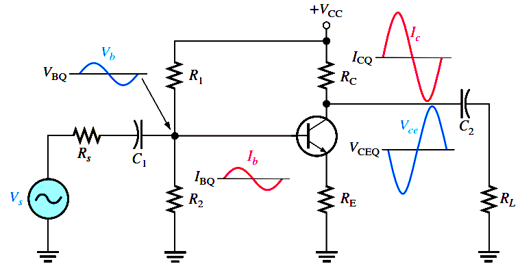
As the sinusoidal collector current increases, the collector voltage decreases. The collector current varies above and below its Q-point value, ICQ, in phase with the base current. The sinusoidal collector-to-emitter voltage varies above and below its Q-point value, VCEQ, 180° out of phase with the base voltage, as illustrated in Figure. A transistor always produces a phase inversion between the base voltage and the collector voltage.

A Graphical Picture

The operation just described can be illustrated graphically on the ac load line, as shown in Below Figure. The sinusoidal voltage at the base produces a base current that varies above and below the Q-point on the ac load line, as shown by the arrows.

Transistor-amplifier-load-line

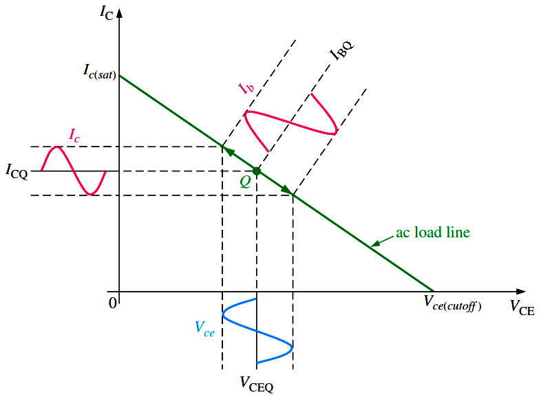
Fig : Graphical ac load line operation of the amplifier showing the variation of the base current, collector current, and collector-to-emitter voltage about their dc Q-point values. Ib and Ic are on different scales.

Lines projected from the peaks of the base current, across to the IC axis, and down to the VCE axis, indicate the peak-to-peak variations of the collector current and collector-to- emitter voltage, as shown. The ac load line differs from the dc load line because the effective ac collector resistance is RL in parallel with RC and is less than the dc collector resistance RC alone.

Don't Miss Our Updates
Be the first to get exclusive content straight to your email.
We promise not to spam you. You can unsubscribe at any time.
Invalid email address
You've successfully subscribed !

Continue Reading

Capacitor Filter Operation
Summary Of Transistor Bias Circuits
What is a Filter Circuit ?
What is Kirchhoff’s Current Law
Ripple Voltage in Rectifiers
Series and Parallel Resistors
Share This Article
Facebook Whatsapp Whatsapp LinkedIn Copy Link
Share
Leave a Comment

Leave a Reply Cancel reply

Your email address will not be published. Required fields are marked *

Stay Connected

128.3kFollowersLike
69.1kFollowersFollow
210kSubscribersSubscribe
38kFollowersFollow

Categories

Explore More

Combining Independent Current Sources in Parallel
Power MOSFET
Resistors Principle & Applications
Full Wave Rectifier
JFET Working Animation
Diode Limiters/Clippers Operation
Cathode Ray Tube Deflection System
Choke Input Filter Operation

Keep Learning

Methods of Transistor Biasing

Methods of Transistor Biasing

Button 3C of the Matrix Keypad is pressed

How the Matrix Keypad works with a Micro controller?

Short Circuit and Open Circuit

Short Circuit and Open Circuit

Transistor Load Line Analysis

Transistor Load Line Analysis

Comparison of Half wave Rectifiers and Full wave Rectifiers

Comparison of Half wave Rectifiers and Full wave Rectifiers

Dependent Voltage Source

Dependent Voltage Source

Reverse Bias Diode Working Animation

Forward Bias & Reverse Bias Diode Working Animation

Transistor as an Amplifier in Common Emitter

Transistor as an Amplifier in Common Emitter

Learn More

Derivation-of-Ohms-Law

Basics of Ohm’s Law

Electric Circuits Objective Questions

Electric Circuits Objective Questions – Set 1

half-wave-rectifier-working-animation

Half Wave Rectifier Principle

Hydrostatic interface level measurement Formula

Hydrostatic Interface Level Measurement

Capacitor Principle

Capacitor

Flow Element Symbol

What is a Flow Element? – Types, Comparison of Flow Elements

Capping Machines

Capping Machine – 5 Aspects of Control Systems and Automation

Pressure Switch Construction

Basics of Pressure switches

Menu

  • About
  • Privacy Policy
  • Copyright

Quick Links

  • Learn PLC
  • Helping Hand
  • Part Time Job

YouTube Subscribe

Follow US
All rights reserved. Reproduction in whole or in part without written permission is prohibited.
Welcome Back!

Sign in to your account

Username or Email Address
Password

Lost your password?