Inst ToolsInst ToolsInst Tools
  • Courses
  • Automation
    • PLC
    • Control System
    • Safety System
    • Communication
    • Fire & Gas System
  • Instrumentation
    • Design
    • Pressure
    • Temperature
    • Flow
    • Level
    • Vibration
    • Analyzer
    • Control Valve
    • Switch
    • Calibration
    • Erection & Commissioning
  • Interview
    • Instrumentation
    • Electrical
    • Electronics
    • Practical
  • Q&A
    • Instrumentation
    • Control System
    • Electrical
    • Electronics
    • Analog Electronics
    • Digital Electronics
    • Power Electronics
    • Microprocessor
  • Request
Search
  • Books
  • Software
  • Projects
  • Process
  • Tools
  • Basics
  • Formula
  • Power Plant
  • Root Cause Analysis
  • Electrical Basics
  • Animation
  • Standards
  • 4-20 mA Course
  • Siemens PLC Course
Reading: Transistor Voltage Divider Bias
Share
Font ResizerAa
Inst ToolsInst Tools
Font ResizerAa
  • Courses
  • Design
  • PLC
  • Interview
  • Control System
Search
  • Courses
  • Automation
    • PLC
    • Control System
    • Safety System
    • Communication
    • Fire & Gas System
  • Instrumentation
    • Design
    • Pressure
    • Temperature
    • Flow
    • Level
    • Vibration
    • Analyzer
    • Control Valve
    • Switch
    • Calibration
    • Erection & Commissioning
  • Interview
    • Instrumentation
    • Electrical
    • Electronics
    • Practical
  • Q&A
    • Instrumentation
    • Control System
    • Electrical
    • Electronics
    • Analog Electronics
    • Digital Electronics
    • Power Electronics
    • Microprocessor
  • Request
Follow US
All rights reserved. Reproduction in whole or in part without written permission is prohibited.
Inst Tools > Blog > Electronic Devices & Circuits > Transistor Voltage Divider Bias

Transistor Voltage Divider Bias

Last updated: September 27, 2016 7:38 am
Editorial Staff
Electronic Devices & Circuits
1 Comment
Share
2 Min Read
SHARE

A method of biasing a transistor for linear operation using a single-source resistive voltage divider. This is the most widely used biasing method.

Transistor Voltage Divider Bias


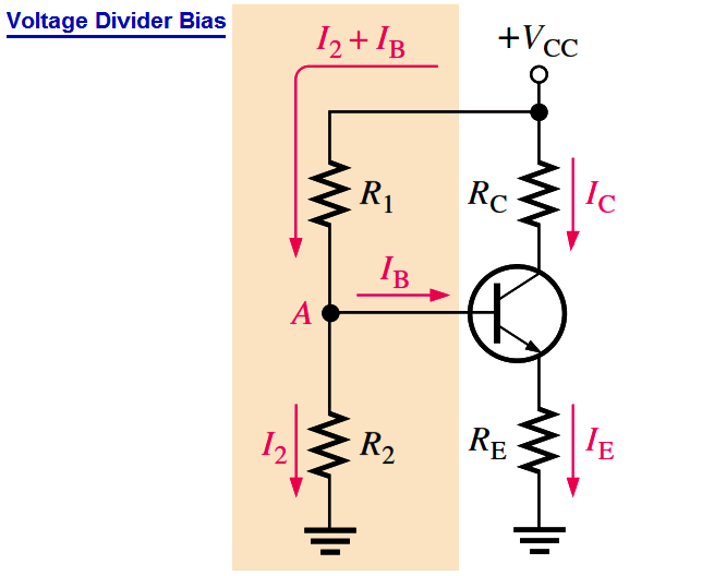
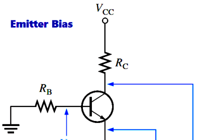
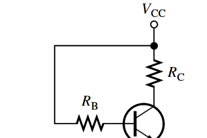
Up to this point a separate dc source, VBB, was used to bias the base-emitter junction because it could be varied independently of VCC and it helped to illustrate transistor operation. A more practical bias method is to use VCC as the single bias source, as shown in the above Figure.

To simplify the schematic, the battery symbol is omitted and replaced by a line termination circle with a voltage indicator (VCC) as shown. A dc bias voltage at the base of the transistor can be developed by a resistive voltage-divider that consists of R1 and R2, as shown in Figure. VCC is the dc collector supply voltage. Two current paths are between point A and ground: one through R2 and the other through the base-emitter junction of the transistor and RE. Generally, voltage-divider bias circuits are designed so that the base current is much smaller than the current (I2) through R2 in Figure.

In this case, the voltage-divider circuit is very straightforward to analyze because the loading effect of the base current can be ignored. A voltage divider in which the base current is small compared to the current in R2 is said to be a stiff voltage divider because the base voltage is relatively independent of different transistors and temperature effects.

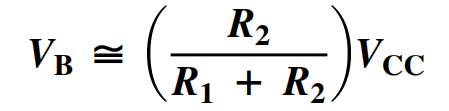
To analyze a voltage-divider circuit in which IB is small compared to I2, first calculate the voltage on the base using the unloaded voltage-divider rule:

voltage-divider-bias-formula


Once you know the base voltage, you can find the voltages and currents in the circuit, as follows:

Transistor-Voltage-divider-bias-formula


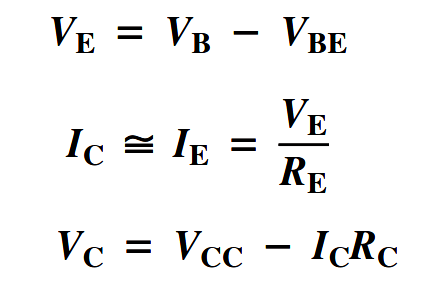
Once you know VC and VE, you can determine VCE.

VCE = VC – VE


Don't Miss Our Updates
Be the first to get exclusive content straight to your email.
We promise not to spam you. You can unsubscribe at any time.
Invalid email address
You've successfully subscribed !

Continue Reading

Basics of Voltage Regulators
What is Kirchhoff’s Voltage Law
Transistor Emitter Feedback Bias
Phototransistor Working Principle
Short Circuit and Open Circuit
Amplifiers Questions & Answers
Share This Article
Facebook Whatsapp Whatsapp LinkedIn Copy Link
Share
1 Comment
  • Sajeendran Sreedharan says:
    December 13, 2021 at 10:33 am

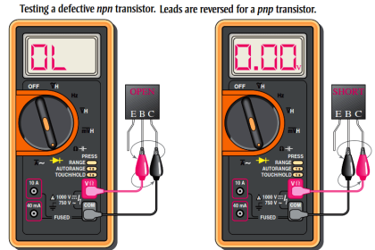
    I would like to know about the instrumentation – how duty cycle of a square wave is measured in a multimeter?

    Reply

Leave a Reply Cancel reply

Your email address will not be published. Required fields are marked *

Stay Connected

128.3kFollowersLike
69.1kFollowersFollow
210kSubscribersSubscribe
38kFollowersFollow

Categories

Explore More

Transistor Stabilisation
Bridge Rectifier Working Animation
Choke Input Filter Operation
Basic Electronics Questions & Answers
Energy Diagrams of PN Junction & Depletion Region
Characteristics of Photo diode
Transistor Cut off, Saturation & Active Regions
Classification of Bridge Circuits

Keep Learning

Independent-Voltage-Source-circuit-ideal-battery

Circuit Elements and Types of Circuits

Schottky Diode Vs PN junction Diode

Difference between Schottky Diode and PN junction Diode

Tunnel Diode

Tunnel Diode Working Principle

Transistor Biasing

Transistor Biasing

Photodiode as Variable Resistance Device

Photodiode as Variable Resistance Device

transistor-terminals

Basics of Transistors

Applications of Photo diodes

Applications of Photo diodes

p-type-semiconductor

N Type and P Type Semiconductors

Learn More

How Valve Positioners act as Cascade Control Systems in a Loop?

How Valve Positioners act as Cascade Control Systems in a Loop?

piping for a Different pressure flow transmitter

Impulse Piping standards for Field instruments

Compressor Cracked Shaft Spacers

Compressor Cracked Shaft Spacers

different types of threads based on 4 standards

Different Types of Threads based on 4 Standards

Difference Between Wifi and Industrial Wireless

Difference Between Wifi and Industrial Wireless

Industrial Gas Detection Systems

PLC based Gas Detection System using Ladder Logic Project

IS Loop Formula

Difference between Intrinsic Safe and Non-Intrinsic Safe Cables

Thermocouples Problem

Fire burnt Ammonia Converter Thermocouples Problem

Menu

  • About
  • Privacy Policy
  • Copyright

Quick Links

  • Learn PLC
  • Helping Hand
  • Part Time Job

YouTube Subscribe

Follow US
All rights reserved. Reproduction in whole or in part without written permission is prohibited.
Welcome Back!

Sign in to your account

Username or Email Address
Password

Lost your password?