Inst ToolsInst ToolsInst Tools
  • Courses
  • Automation
    • PLC
    • Control System
    • Safety System
    • Communication
    • Fire & Gas System
  • Instrumentation
    • Design
    • Pressure
    • Temperature
    • Flow
    • Level
    • Vibration
    • Analyzer
    • Control Valve
    • Switch
    • Calibration
    • Erection & Commissioning
  • Interview
    • Instrumentation
    • Electrical
    • Electronics
    • Practical
  • Q&A
    • Instrumentation
    • Control System
    • Electrical
    • Electronics
    • Analog Electronics
    • Digital Electronics
    • Power Electronics
    • Microprocessor
  • Request
Search
  • Books
  • Software
  • Projects
  • Process
  • Tools
  • Basics
  • Formula
  • Power Plant
  • Root Cause Analysis
  • Electrical Basics
  • Animation
  • Standards
  • 4-20 mA Course
  • Siemens PLC Course
Reading: Basic Requirements of Control Valves Sizing
Share
Font ResizerAa
Inst ToolsInst Tools
Font ResizerAa
  • Courses
  • Design
  • PLC
  • Interview
  • Control System
Search
  • Courses
  • Automation
    • PLC
    • Control System
    • Safety System
    • Communication
    • Fire & Gas System
  • Instrumentation
    • Design
    • Pressure
    • Temperature
    • Flow
    • Level
    • Vibration
    • Analyzer
    • Control Valve
    • Switch
    • Calibration
    • Erection & Commissioning
  • Interview
    • Instrumentation
    • Electrical
    • Electronics
    • Practical
  • Q&A
    • Instrumentation
    • Control System
    • Electrical
    • Electronics
    • Analog Electronics
    • Digital Electronics
    • Power Electronics
    • Microprocessor
  • Request
Follow US
All rights reserved. Reproduction in whole or in part without written permission is prohibited.
Inst Tools > Blog > Control Valves > Basic Requirements of Control Valves Sizing

Basic Requirements of Control Valves Sizing

Last updated: March 21, 2019 11:23 pm
Editorial Staff
Control Valves Instrumentation Design
2 Comments
Share
5 Min Read
SHARE

A control valve is a power operated device capable of modulating  flow at varying degrees between minimal flow and full capacity in response to a signal from the controlling system. Control valves may be broadly classified by their function as “on-off” type or “flow regulating” type.

Contents
Control Valves SizingTIPS AND TRICKS

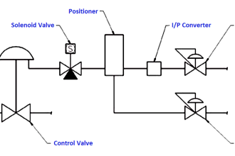
A control  valve  is comprised  of an  actuator  mechanism  that  is capable  of changing  the position of flow controlling element in the valve. The valve modulates flow through movement of a valve plug in relation  to the port(s)  located  within  the valve body. The valve  plug is attached to a valve stem, which, in turn, is connected to the actuator.

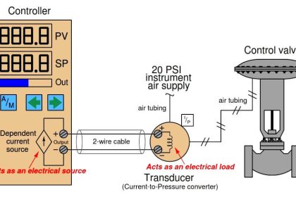
The actuator, which can be pneumatically  or electrically operated, directs the movement of the stem as dictated by the external  control  device.  The actuator  responds  to an external  signal which usually comes from a controller. The controller and valve together form a basic control loop.

There are many types of valves available, each having their advantages and limitations.

Control Valves Sizing

The basic requirements  and selection depend on their ability to perform specific functions such as:

  1. Ability to throttle or control the rate of flow;
  2. Lack of turbulence or resistance to flow when fully open – turbulence reduces head pressure;
  3. Quick opening and closing mechanism – rapid response is many times needed in an emergency or for safety;
  4. Tight shut off – prevents leaks against high pressure;
  5. Ability to allow flow in one direction only – prevents return;
  6. Opening at a preset pressure – procedure control to prevent equipment damage; and
  7. Ability to handle abrasive fluids – hardened material prevents rapid wear.

TIPS AND TRICKS

Take the following tips into consideration when choosing a valve.

  1. Choose a valve that will pass the maximum flow when about 90% open.
  1. Choose a valve that will pass the minimum flow when about 10% open.
  1. Choose a valve that will pass the normal flow when about 60-70% open.
  1. Size control valves to absorb about 1/3rd of the total system pressure drop.
  1. Control valves  should  not  be  less  than  half  the  pipe  size.  Normally  the  valves exclusively envisaged for shut-off service shall be line size. Alternatively,  they could be sized as control valves.
  1. In the case of lines with a diameter of up to 1″ the valve size shall normally equal that of the line. In the case of lines with a diameter larger than 1″ the valve size shall not be less than 1″.
  1. Valves shall generally have flanged connections  as per rating envisaged in the line specification  with the exception  of valves  with a nominal  diameter  smaller  than or equal to 1½” which shall have a minimum rating of 300 ANSI.
  1. If you are dealing with a corrosive fluid, choose the valve body and trim material to match the pump casing and impeller.
  1. Velocity is the key to handling abrasive materials. Keep line velocity of about 10 ft/s for  clean  liquid.  If you  have  a fluid  that  is abrasive,  keep  the  velocity  as  low  as possible, without having the particles drop out of suspension. When dealing with high pressure drop situations try always to keep the velocities below 0.3 mach on the inlet pipe, valve body, and outlet pipe.
  1. Always sense pressure  where  you  want  to  control  it.  Many  control  valves  and pressure  regulators  do  not  function  properly  simply  because  they  are  sensing pressure at one point and being asked to control it somewhere else.
  1. If you use a transducer in a control loop, specify a positioner on the valve. Otherwise the transducer will rob the actuator of available thrust, and the valve will leak when it is supposed to shut off.
  1. In cavitating fluids “be sure to allow a straight run of downstream pipe after the valve – even when the control valve has cavitation trim in it”. If there is a pipe “T” or elbow immediately downstream, the flow will choke out and back up into the valve.
  1. Remember that control  valves  only  do what  you  tell them  to. Many  control  valve problems turn out to be a problem somewhere else.

Articles You May Like :

Actuator Fail Safe Mode

Control Valve Animation

Basics of Globe Valves

Trip Valve Principle

Valves Chemical Problems

Don't Miss Our Updates
Be the first to get exclusive content straight to your email.
We promise not to spam you. You can unsubscribe at any time.
Invalid email address
You've successfully subscribed !

Continue Reading

Pneumatic Valves and Cylinders Sizing – Part 2
Ferrules and Cross Ferruling
Electronic Valve positioners
Pneumatic Cylinder Air Flow Calculation
Working of Rupture Disk
Control Valve Recommended Practices for Harsh Process Conditions
Share This Article
Facebook Whatsapp Whatsapp LinkedIn Copy Link
Share
2 Comments
  • karim says:
    October 22, 2016 at 5:58 pm

    Hi sir,
    first thank you this useful website and also the app.
    Could you please explain more the tip No 7?

    thanks

    Reply
  • Virendra Kumar says:
    May 11, 2018 at 9:20 am

    Thanks sir

    Reply

Leave a Reply Cancel reply

Your email address will not be published. Required fields are marked *

Stay Connected

128.3kFollowersLike
69.1kFollowersFollow
210kSubscribersSubscribe
38kFollowersFollow

Categories

Explore More

How to Select a Flow Meter
Pressure Safety Valve Leak Test Procedure (PSV Testing)
Working Principle of Self Operated Valves
Signal Coupling and Cable Separation
Dampers and Louvres
Speed of Actuators
Instrumentation Books Download
Summary of Valve Types Characteristics

Keep Learning

Tie rods double acting cylinder

What is a Pneumatic Cylinder?

Cable Tray Routing

Cable Routing

Globe Valve Disk and Stem Connections

Globe Valve Seat and Disk

solenoid-valves-types-principle-animation

Solenoid Valves Types, Principle & Animation

Piping Schematic for Two Solenoid Valves Double Acting

Different Types of Control Valve Actuators

Piston Check Valve

What is Piston Check Valve ?

Control valve sizing

Basics of Control Valve Sizing

3-way-2-position-solenoid-valve-spring-return

Pneumatic Directional Control Valves

Learn More

Instrumentation Standards

Electronic Equipment Purging Principles & Standards

Single Port Globe Valve

How Sliding Stem Valves Work ?

Cable Glands

Using of MCT instead of Cable Glands on the Cabinets

PLC railway crossing program

Automatic Railway Crossing Gate Control PLC Program

4-20mA Loop Power Supply Questions

4-20mA Loop Power Supply Questions and Answers

capacitor-filter-ripples

Ripple Voltage in Rectifiers

Instrumentation Engineer’s Calibration Mistakes

Safety Instrumented System Engineer Interview Questions

Safety Instrumented Systems Online Exam

Menu

  • About
  • Privacy Policy
  • Copyright

Quick Links

  • Learn PLC
  • Helping Hand
  • Part Time Job

YouTube Subscribe

Follow US
All rights reserved. Reproduction in whole or in part without written permission is prohibited.
Welcome Back!

Sign in to your account

Username or Email Address
Password

Lost your password?