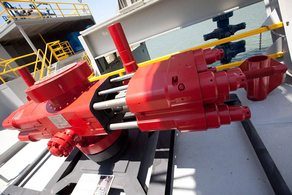
A blowout preventer (BOP) is a large, specialized valve or similar mechanical device, used to seal, control and monitor oil and gas wells to prevent blowouts, the uncontrolled release of crude oil and/or natural gas from a well. They are usually installed in stacks of other valves.
Blowout preventers were developed to cope with extreme erratic pressures and uncontrolled flow (formation kick) emanating from a well reservoir during drilling. Kicks can lead to a potentially catastrophic event known as a blowout. In addition to controlling the downhole (occurring in the drilled hole) pressure and the flow of oil and gas, blowout preventers are intended to prevent tubing (e.g. drill pipe and well casing), tools and drilling fluid from being blown out of the wellbore (also known as bore hole, the hole leading to the reservoir) when a blowout threatens.
Blowout preventers are critical to the safety of crew, rig (the equipment system used to drill a wellbore) and environment, and to the monitoring and maintenance of well integrity; thus blowout preventers are intended to provide fail-safety to the systems that include them.
The term BOP (pronounced B-O-P, not “bop”) is used in oilfield vernacular to refer to blowout preventers. The abbreviated term preventer, usually prefaced by a type (e.g. ram preventer), is used to refer to a single blowout preventer unit. A blowout preventer may also simply be referred to by its type (e.g. ram).
The terms blowout preventer, blowout preventer stack and blowout preventer system are commonly used interchangeably and in a general manner to describe an assembly of several stacked blowout preventers of varying type and function, as well as auxiliary components. A typical subsea deepwater blowout preventer system includes components such as electrical and hydraulic lines, control pods, hydraulic accumulators, test valve, kill and choke lines and valves, riser joint, hydraulic connectors, and a support frame.
Principle
Blowout preventers are used on land wells, offshore rigs, and subsea wells. Land and subsea BOPs are secured to the top of the wellbore, known as the wellhead. BOPs on offshore rigs are mounted below the rig deck. Subsea BOPs are connected to the offshore rig above by a drilling riser that provides a continuous pathway for the drill string and fluids emanating from the wellbore. In effect, a riser extends the wellbore to the rig. Unfortunately, blowout preventers do not always function correctly. An example of this is the Deepwater Horizon blowout, where the pipe line going through the BOP was slightly bent and the BOP failed to cut the pipe.
In drilling a typical high-pressure well, drill strings are routed through a blowout preventer stack toward the reservoir of oil and gas. As the well is drilled, drilling fluid, “mud”, is fed through the drill string down to the drill bit, “blade”, and returns up the wellbore in the ring-shaped void, annulus, between the outside of the drill pipe and the casing (piping that lines the wellbore). The column of drilling mud exerts downward hydrostatic pressure to counter opposing pressure from the formation being drilled, allowing drilling to proceed.
When a kick (influx of formation fluid) occurs, rig operators or automatic systems close the blowout preventer units, sealing the annulus to stop the flow of fluids out of the wellbore. Denser mud is then circulated into the wellbore down the drill string, up the annulus and out through the choke line at the base of the BOP stack through chokes (flow restrictors) until downhole pressure is overcome. Once “kill weight” mud extends from the bottom of the well to the top, the well has been “killed”.
If the integrity of the well is intact drilling may be resumed. Alternatively, if circulation is not feasible it may be possible to kill the well by “bullheading”, forcibly pumping, in the heavier mud from the top through the kill line connection at the base of the stack. This is less desirable because of the higher surface pressures likely needed and the fact that much of the mud originally in the annulus must be forced into receptive formations in the open hole section beneath the deepest casing shoe.
If the blowout preventers and mud do not restrict the upward pressures of a kick, a blowout results, potentially shooting tubing, oil and gas up the wellbore, damaging the rig, and leaving well integrity in question.
Since BOPs are important for the safety of the crew and natural environment, as well as the drilling rig and the wellbore itself, authorities recommend, and regulations require, that BOPs be regularly inspected, tested and refurbished. Tests vary from daily test of functions on critical wells to monthly or less frequent testing on wells with low likelihood of control problems.
Exploitable reservoirs of oil and gas are increasingly rare and remote, leading to increased subsea deepwater well exploration and requiring BOPs to remain submerged for as long as a year in extreme conditions. As a result, BOP assemblies have grown larger and heavier (e.g. a single ram-type BOP unit can weigh in excess of 30,000 pounds), while the space allotted for BOP stacks on existing offshore rigs has not grown commensurately. Thus a key focus in the technological development of BOPs over the last two decades has been limiting their footprint and weight while simultaneously increasing safe operating capacity.
Types
Two categories of blowout preventer are most prevalent:
- Ram
- Annular.
BOP stacks frequently utilize both types, typically with at least one annular BOP stacked above several ram BOPs.
Types of Controlling methods
When wells are drilled on land or in very shallow water where the wellhead is above the water line, BOPs are activated by hydraulic pressure from a remote accumulator. Several control stations will be mounted around the rig. They also can be closed manually by turning large wheel-like handles.
In deeper offshore operations with the wellhead just above the mudline on the sea floor, there are five primary ways by which a BOP can be controlled. The possible means are:
- Hydraulic Control Signal: sent from surface through a hydraulic umbilical;
- Electrical Control Signal: sent from the surface through a control cable;
- Acoustical Control Signal: sent from the surface based on a modulated/encoded pulse of sound transmitted by an underwater transducer;
- ROV Intervention: remotely operated vehicles (ROVs) mechanically control valves and provide hydraulic pressure to the stack (via “hot stab” panels);
- Deadman Switch / Auto Shear: fail-safe activation of selected BOPs during an emergency, and if the control, power and hydraulic lines have been severed.
Two control pods are provided on the BOP for redundancy. Electrical signal control of the pods is primary. Acoustical, ROV intervention and dead-man controls are secondary.
An emergency disconnect system/sequence, or EDS, disconnects the rig from the well in case of an emergency. The EDS is also intended to automatically trigger the deadman switch, which closes the BOP, kill and choke valves. The EDS may be a subsystem of the BOP stack’s control pods or separate.
Pumps on the rig normally deliver pressure to the blowout preventer stack through hydraulic lines. Hydraulic accumulators are on the BOP stack enable closure of blowout preventers even if the BOP stack is disconnected from the rig. It is also possible to trigger the closing of BOPs automatically based on too high pressure or excessive flow.
Applications
Blowout preventers come in a variety of styles, sizes and pressure ratings. Several individual units serving various functions are combined to compose a blowout preventer stack. Multiple blowout preventers of the same type are frequently provided for redundancy, an important factor in the effectiveness of fail-safe devices.
The primary functions of a blowout preventer system are to:
- Confine well fluid to the wellbore;
- Provide means to add fluid to the wellbore;
- Allow controlled volumes of fluid to be withdrawn from the wellbore.
Additionally, and in performing those primary functions, blowout preventer systems are used to:
- Regulate and monitor wellbore pressure;
- Center and hang off the drill string in the wellbore;
- Shut in the well (e.g. seal the void, annulus, between drillpipe and casing);
- “Kill” the well (prevent the flow of formation fluid, influx, from the reservoir into the wellbore) ;
- Seal the wellhead (close off the wellbore);
- Sever the casing or drill pipe (in case of emergencies).
Reference : Wikipedia