Inst ToolsInst ToolsInst Tools
  • Courses
  • Automation
    • PLC
    • Control System
    • Safety System
    • Communication
    • Fire & Gas System
  • Instrumentation
    • Design
    • Pressure
    • Temperature
    • Flow
    • Level
    • Vibration
    • Analyzer
    • Control Valve
    • Switch
    • Calibration
    • Erection & Commissioning
  • Interview
    • Instrumentation
    • Electrical
    • Electronics
    • Practical
  • Q&A
    • Instrumentation
    • Control System
    • Electrical
    • Electronics
    • Analog Electronics
    • Digital Electronics
    • Power Electronics
    • Microprocessor
  • Request
Search
  • Books
  • Software
  • Projects
  • Process
  • Tools
  • Basics
  • Formula
  • Power Plant
  • Root Cause Analysis
  • Electrical Basics
  • Animation
  • Standards
  • 4-20 mA Course
  • Siemens PLC Course
Reading: Automatic Railway Crossing Gate Control PLC Program
Share
Font ResizerAa
Inst ToolsInst Tools
Font ResizerAa
  • Courses
  • Design
  • PLC
  • Interview
  • Control System
Search
  • Courses
  • Automation
    • PLC
    • Control System
    • Safety System
    • Communication
    • Fire & Gas System
  • Instrumentation
    • Design
    • Pressure
    • Temperature
    • Flow
    • Level
    • Vibration
    • Analyzer
    • Control Valve
    • Switch
    • Calibration
    • Erection & Commissioning
  • Interview
    • Instrumentation
    • Electrical
    • Electronics
    • Practical
  • Q&A
    • Instrumentation
    • Control System
    • Electrical
    • Electronics
    • Analog Electronics
    • Digital Electronics
    • Power Electronics
    • Microprocessor
  • Request
Follow US
All rights reserved. Reproduction in whole or in part without written permission is prohibited.
Inst Tools > Blog > PLC Tutorials > Automatic Railway Crossing Gate Control PLC Program

Automatic Railway Crossing Gate Control PLC Program

Learn how to create a PLC program for automatic railway crossing gate control using sensors to detect trains and ensure safe gate operation.

Last updated: October 1, 2024 5:24 am
Editorial Staff
PLC Tutorials
No Comments
Share
6 Min Read
SHARE

This article discusses the PLC program to control the Railway Crossing system automatically. This Railway Crossing Gate system is used to ensure the safety of road users when trains pass. The railway crossing gate system will automatically close the crossing gate and activate the alarm when an oncoming train is detected. After the train passes the crossing, the crossing gate will Open again and the alarm will be turned Off.

Contents
Automatic Railway Crossing GateAddressingPLC Program

Automatic Railway Crossing Gate

This system has 2 sequences, When the train comes and when the train has Passed :

Sequence-1: WHEN THE TRAIN COMES

When the SENS_TRAIN_COME (0.02) sensor detects a train coming, the moving Crossing Gate closes and the warning alarm will be ON.

The Crossing Gate Stops closing when the SENS_GATE_DOWN (0.03) sensor is Active.

Sequence-2: WHEN THE TRAIN HAS PASSED

The SENS_TRAIN_LEFT (0.04) sensor will be Active when it detects that a train has passed a train crossing.

5 seconds after the SENS_TRAIN_LEFT (0.04) sensor is Active, the Crossing Gate will OPEN.

The Crossing Gate opening system is made with a 5-second delay to ensure the train has passed the Crossing Gate.

The crossing gate will Stop opening when the SENS_GATE_UP (0.05) sensor is Active.

The OUT_ALARM (100.02) alarm will be OFF when the Crossing Gate Stops moving OPEN.

Automatic Railway Crossing Gate Control PLC Program

Addressing

CommentInput (I)Output (Q)Memory BitsTimer
START_SYSTEM0.00   
STOP_SYSTEM0.01   
SENS_TRAIN_COME0.02   
SENS_GATE_DOWN0.03   
SENS_TRAIN_LEFT0.04   
SENS_GATE_UP0.05   
OUT_GATE_DOWN 100.00  
OUT_GATE_UP 100.01  
OUT_ALARM 100.02  
SYSTEM_ON  W0.00 
IR_GATE_DOWN  W0.01 
IR_GATE_UP  W0.02 
IR_ALARM  W0.03 
TIMER_1   T0000

PLC Program

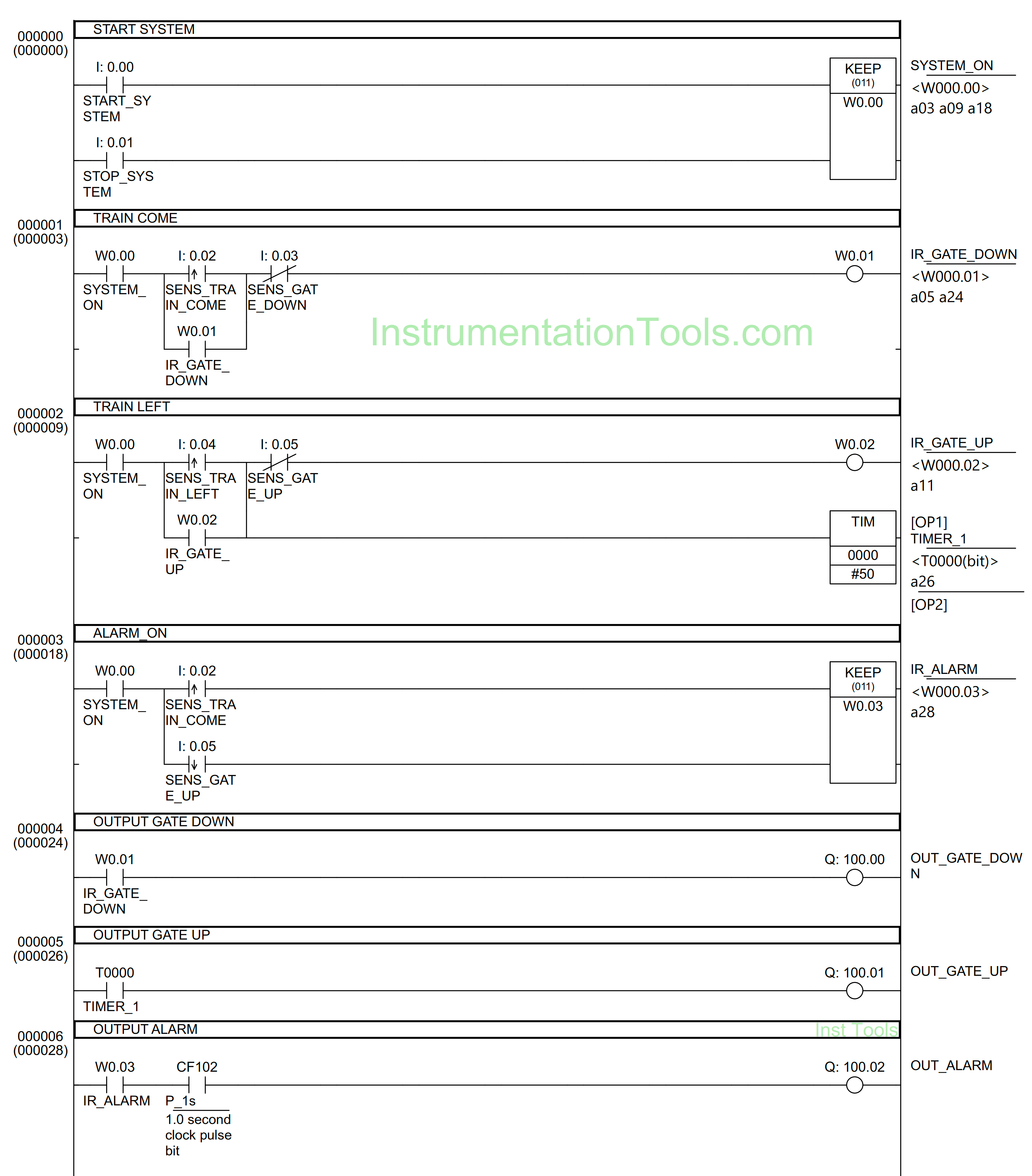
RUNG 0 (START SYSTEM)

In this Rung, when the START_SYSTEM (0.00) button is pressed, the memory bit SYSTEM_ON (W0.00) will be in the HIGH state. Because the KEEP(011) instruction is used, the memory bit SYSTEM_ON (W0.00) remains in the HIGH state even though the START_SYSTEM (0.00) button has been Released.

The memory bit SYSTEM_ON (W0.00) will become a LOW state if the STOP_SYSTEM (0.01) button is Pressed.
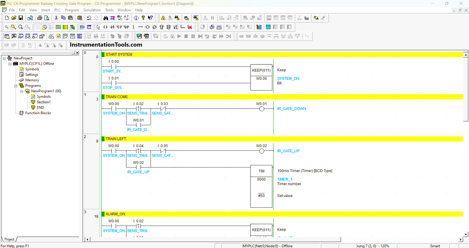
PLC railway crossing program

RUNG 1 (TRAIN COME)

In this Rung, when the NO contact of memory bit SYSTEM_ON (W0.00) and the SENS_TRAIN_COME (0.02) sensor in the HIGH state, then the memory bit IR_GATE_DOWN (W0.01) will be in the HIGH state.

Because it uses Latching, the memory bit IR_GATE_DOWN (W0.01) will remain in the HIGH state even though the SENS_TRAIN_COME (0.02) sensor is in the LOW state.

The memory bit IR_GATE_DOWN (W0.01) will be in the LOW state if the NC contact of the SENS_GATE_DOWN (0.03) sensor is in the HIGH state.

RUNG 2 (TRAIN LEFT)

In this Rung, when the NO contact of memory bit SYSTEM_ON (W0.00) and the SENS_TRAIN_LEFT (0.04) sensor in the HIGH state, then the memory bit IR_GATE_UP (W0.02) will be in the HIGH state and the TIMER_1 (T0000) timer Starts counting up to 5 seconds.

Because it uses Latching, the memory bit IR_GATE_UP (W0.02) will remain in the HIGH state even though the SENS_TRAIN_LEFT (0.04) sensor is in the LOW state.

The memory bit IR_GATE_UP (W0.02) will be in a LOW state if the NC contact of the SENS_GATE_UP (0.05) sensor is in the HIGH state.

RUNG 3 (ALARM ON)

In this Rung, when the NO contact of memory bit SYSTEM_ON (W0.00) and the SENS_TRAIN_COME (0.02) sensor in the HIGH state, then the memory bit IR_ALARM (W0.03) will be in the HIGH state. Because it uses the KEEP(011) instruction, the memory bit IR_ALARM (W0.03) remains in the HIGH state even though the SENS_TRAIN_COME (0.02) sensor is in the LOW state.

When the SENS_GATE_UP (0.05) sensor is in the HIGH state, the memory bit IR_ALARM (W0.03) will be in the LOW state.

Automatic gate control with PLC

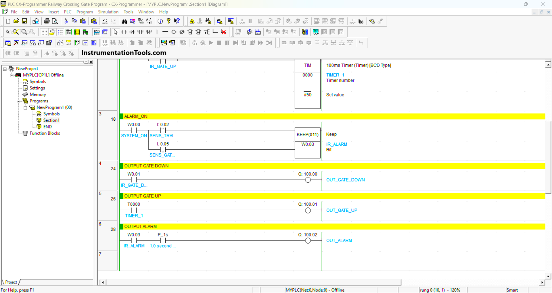
RUNG 4 (OUTPUT GATE DOWN)

In this Rung, when the NO contact of memory bit IR_GATE_DOWN (W0.01) is in the HIGH state, the output OUT_GATE_DOWN (100.00) will be ON.

RUNG 5 (OUTPUT GATE UP)

In this Rung, when the NO contact of timer TIMER_1 (T0000) is in the HIGH state, the output OUT_GATE_UP (100.01) will be ON.

RUNG 6 (ALARM OUTPUT)

In this Rung, when the NO contact of memory bit IR_ALARM (W0.03) is in the HIGH state, the output OUT_ALARM (100.02) will be ON.

the output OUT_ALARM (100.02) output will be ON blinking with an interval of 1 second, because of the NO contact of P_1s (1.0-second clock pulse bit).

Read Next:

  • PLC Program for Mailbox with Counting
  • Dosing Pump PLC Programming Logic
  • Schneider Electric PLC Timer Problems
  • PLC Programming 3 Motors with Priority
  • PLC Crane Movement Control Program

Don't Miss Our Updates
Be the first to get exclusive content straight to your email.
We promise not to spam you. You can unsubscribe at any time.
Invalid email address
You've successfully subscribed !

Continue Reading

Relay Operation, Types, Symbols & Characteristics
Create User-Defined Data Types and Function Blocks in Studio 5000
Various Communication Protocols in PLC
Cars Garage Counter From the Same Door PLC Logic
What is Masking in PLC?
1oo2 Evaluation Safety Instruction in Safety PLC
Share This Article
Facebook Whatsapp Whatsapp LinkedIn Copy Link
Share
Leave a Comment

Leave a Reply Cancel reply

Your email address will not be published. Required fields are marked *

Stay Connected

128.3kFollowersLike
69.1kFollowersFollow
210kSubscribersSubscribe
38kFollowersFollow

Categories

Explore More

Flexible Input Output Modules
Real-time PLC Projects – Industrial Automation
PLC Program using START and STOP Buttons
Introduction to Functional Block Diagram in Studio 5000
How to Export Data from WinCC Runtime Advanced into Excel using VB Script
VFD Simulator Download – Free Yaskawa V1000 Software
XG5000 Example of Simple Conveyor Control PLC Program
PLC Light Sequence Control using Bit Shift Registers

Keep Learning

PLC Program for Washing Machine

PLC Program for Washing Machine

PLC project for traffic signals automation

Complete PLC Project: Traffic Light Auto and Manual Automation

PLC Data Logging and Transmission

Moving Data between PLCs – Siemens Basics – TSEND TRCV

PLC Program for Automatic Bottle Rejection System

PLC Program for Automatic Bottle Rejection System

How to Design a Motor Faceplate in Graphics - SCADA Tutorials

How to Design a Motor Faceplate in Graphics? – SCADA Tutorials

Analog Instruments

Explaining Various Types of Analog Instruments

Omron PLC painting program

Product Painting PLC Program using Omron CX-Programmer

Electrical Circuit Label Schematic

Label the Electrical Circuit Schematic

Learn More

Transformers Questions & Answers Part-2

Transformers Questions & Answers Part-2

Hammer Effect in Gauges

What is Hammer Effect in Gauges ?

Measurement and Instrumentation Objective Questions

Measurements & Instrumentation Quiz – Set 7

PID-Controller-Simulator-graph

PID Controller Tunning Parameters Simulator

Helix and Spiral Tubes - Pressure Sensor

Helix and Spiral Tubes – Pressure Sensor

Galileo thermometer Principle

Galileo Thermometer

Top 50 Electrical Engineering Questions & Answers

Top 50 Electrical Engineering Questions & Answers

Combining Independent Voltage Sources in Series

Combining Independent Voltage Sources in Series

Menu

  • About
  • Privacy Policy
  • Copyright

Quick Links

  • Learn PLC
  • Helping Hand
  • Part Time Job

YouTube Subscribe

Follow US
All rights reserved. Reproduction in whole or in part without written permission is prohibited.
Welcome Back!

Sign in to your account

Username or Email Address
Password

Lost your password?