This article is about the PLC programming for the Alarm acknowledge logic.
In most industries, a standard procedure will be followed for alarm management. Some critical processes running in the industries may cause faults due to some failure of equipment, out-of-control process loops, etc.
Fault can be generated when some measured variable goes out of the range, this can be level, flow, temperature, pressure or any other kind of parameter.
Below discussed the example PLC program to acknowledge the alarms using Siemens TIA portal ladder logic.
Problem
When there is a fault (I0.0) then alarm (Q0.0) should start blinking. When there is a fault signal, if the acknowledge button (I0.1) is pressed then the alarm will change from blinking to constant mode, means still there is a fault.
When the fault has gone, the alarm indication goes off.
Inputs
- FAULT (I0.0)
- ALARM ACKNOWLEDGE (I0.1)
Outputs
- ALARM INDICATION (Q0.0)
Alarm Acknowledge using PLC
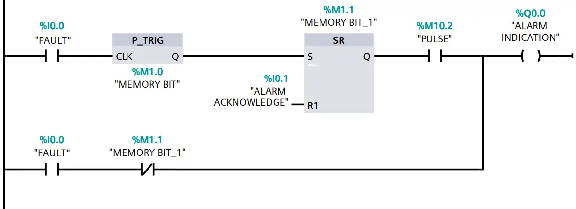
Logic Description
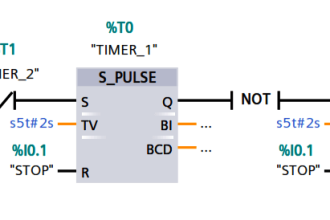
When the fault is generated, I0.0 becomes true, which allows the signal to pass through a positive edge detector which only allows the cycle to execute only once. After this signal goes to SR flip-flop where due to set has higher priority, the signal will be latched.
This signal will be passed through the clock pulse (M10.2 in our case), this generated the flashing alarm indicator.
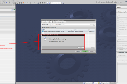
(note: here I have use bit M10.2 which is used to generate clock pulses.)
To select this bit, follow the step shown in the below figure.
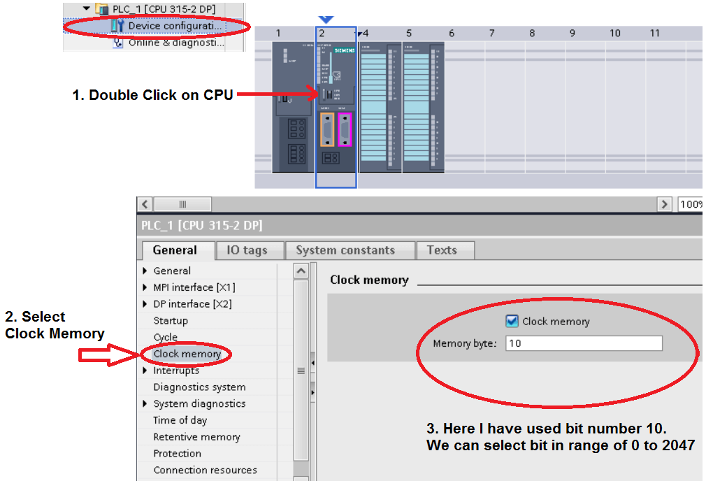
(another thing to note is that the number after decimal point indicate the rate of frequency, lower the number higher the frequency, like in our case after 10 there is 0.2 which indicate the rate of frequency or flashing rate like blinking LED.)
In the second rung, the Fault input status is in series with active memory bit of SR flip-flop (NC contact), which allows the signal to pass when the alarm is acknowledged. When the fault is normalized then the alarm indication goes off.
Author: Suhel Patel
If you liked this article, then please subscribe to our YouTube Channel for PLC and SCADA video tutorials.
You can also follow us on Facebook and Twitter to receive daily updates.
Read Next:
- Problem on PLC, VFD, Motor
- Connect to the Siemens S7 PLC
- Instrument Percent of Span Error
- Types of Interlocks
- Analog and Digital Signals
