Inst ToolsInst ToolsInst Tools
  • Courses
  • Automation
    • PLC
    • Control System
    • Safety System
    • Communication
    • Fire & Gas System
  • Instrumentation
    • Design
    • Pressure
    • Temperature
    • Flow
    • Level
    • Vibration
    • Analyzer
    • Control Valve
    • Switch
    • Calibration
    • Erection & Commissioning
  • Interview
    • Instrumentation
    • Electrical
    • Electronics
    • Practical
  • Q&A
    • Instrumentation
    • Control System
    • Electrical
    • Electronics
    • Analog Electronics
    • Digital Electronics
    • Power Electronics
    • Microprocessor
  • Request
Search
  • Books
  • Software
  • Projects
  • Process
  • Tools
  • Basics
  • Formula
  • Power Plant
  • Root Cause Analysis
  • Electrical Basics
  • Animation
  • Standards
  • 4-20 mA Course
  • Siemens PLC Course
Reading: Air Compressor Control Circuit Problem
Share
Font ResizerAa
Inst ToolsInst Tools
Font ResizerAa
  • Courses
  • Design
  • PLC
  • Interview
  • Control System
Search
  • Courses
  • Automation
    • PLC
    • Control System
    • Safety System
    • Communication
    • Fire & Gas System
  • Instrumentation
    • Design
    • Pressure
    • Temperature
    • Flow
    • Level
    • Vibration
    • Analyzer
    • Control Valve
    • Switch
    • Calibration
    • Erection & Commissioning
  • Interview
    • Instrumentation
    • Electrical
    • Electronics
    • Practical
  • Q&A
    • Instrumentation
    • Control System
    • Electrical
    • Electronics
    • Analog Electronics
    • Digital Electronics
    • Power Electronics
    • Microprocessor
  • Request
Follow US
All rights reserved. Reproduction in whole or in part without written permission is prohibited.
Inst Tools > Blog > Practical Questions > Air Compressor Control Circuit Problem

Air Compressor Control Circuit Problem

The air compressor control circuit has a problem and unable to start even when the air pressure is zero PSI.

Last updated: October 23, 2020 11:20 am
Editorial Staff
Practical Questions
No Comments
Share
3 Min Read
SHARE

This air compressor control circuit has a problem. The air compressor refuses to start even when the air pressure is zero PSI.

Air Compressor Control Circuit

Air Compressor Control Circuit has a Problem

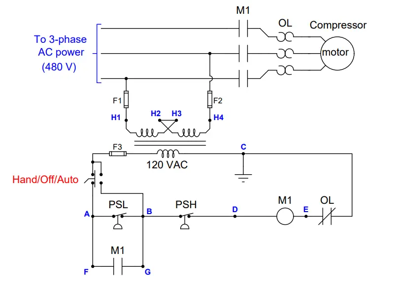
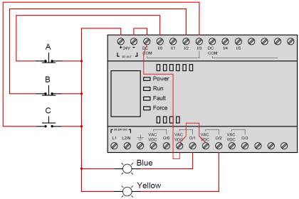
A technician begins diagnosing the circuit, following the steps shown (in order):

Test 1: Measured 120 VAC between points A and C, with “Hand/Off/Auto” switch in the “Auto” position.

Test 2: Measured 120 VAC between points A and D, with “Hand/Off/Auto” switch in “Auto” position.

Test 3: Measured 0 VAC between points E and C, with “Hand/Off/Auto” switch in “Auto” position.

Test 4: Jumpered points A and B, with “Hand/Off/Auto” switch in “Auto” position. The motor did not start.

Identify any useful information about the nature or location of the fault derived from the results of each test, in order of the tests performed. If the test is not useful (i.e. provides no new information), mark it as such.

Assuming there is only one fault in the circuit, identify the location and nature of the fault as precisely as you can from the test results shown above.

Answer:

Test 1: Measured 120 VAC between points A and C, with “Hand/Off/Auto” switch in the “Auto” position. Proves there is 120 VAC control power available, that the fuse is good, and that the Hand/Off/Auto switch is passing power through to point A.

Test 2: Measured 120 VAC between points A and D, with “Hand/Off/Auto” switch in “Auto” position. Proves there is an “open” fault somewhere between those points, in one of the two switches, and that we do not have any other “open” faults in the contactor coil circuit.

Test 3: Measured 0 VAC between points E and C, with “Hand/Off/Auto” switch in “Auto” position. This is an unnecessary test, as we already know there is continuity through the overload contact.

Test 4: Jumpered points A and B, with “Hand/Off/Auto” switch in “Auto” position. The motor did not start. Combined with the results of previous tests, this test proves the “open” fault must lie between points B and D: namely the PSH.

The fault is an “open” high pressure switch (PSH), or in the wires connecting the PSH to points B and D.

Share your answers with us through the below comments section.

Read Next:

  • Compressor Seal Oil System
  • PLC Compressor Logic
  • Instrument Air Compressor
  • Liquid Level Switch Control
  • PLC Water Level Control Logic

Credits: Tony R. Kuphaldt

Don't Miss Our Updates
Be the first to get exclusive content straight to your email.
We promise not to spam you. You can unsubscribe at any time.
Invalid email address
You've successfully subscribed !

Continue Reading

Determine the Problems with Level Transmitter and Gauge
Programmable Logic Controller (PLC) Questions and Answers – 13
Solenoid Valves Practical Problems
Pneumatic Relay Questions
Identify Solenoid Valves Energized or de-energized?
Problem on Tachogenerator
Share This Article
Facebook Whatsapp Whatsapp LinkedIn Copy Link
Share
Leave a Comment

Leave a Reply Cancel reply

Your email address will not be published. Required fields are marked *

Stay Connected

128.3kFollowersLike
69.1kFollowersFollow
210kSubscribersSubscribe
38kFollowersFollow

Categories

Explore More

Practical Process Control System Questions & Answers – 2
Flapper Nozzle Questions
Which Instrument is Faulty? Transmitter, Recorder, or Controller
Galileo Thermometer
Displacer Level Transmitter Question & Answer
Hydrostatic Pressure Measurement Questions
Identify Faults in PID Control Loop
Heat Exchanger Differential Pressure Transmitter

Keep Learning

Pressure-sensing level transmitter

Moving Pressure Sensing Level Transmitter from Top to Bottom

Calculate DPT Calibrated Range

Calculate the Transmitter Values

surface-mounted water pump

Surface-mounted Water Pump

PLC Circuit Answers

PLC connected to Three Pushbutton Switches

DP Transmitter Located 10 feet Beneath the Vessel

DP Transmitter Located 10 feet Beneath the Vessel

Steam flow to the heat exchanger

Analytical Process Control Question

Is it Possible to Measure liquid-liquid Level Interface using Float

Is it Possible to Measure Liquid-Liquid Level Interface using Float?

water filter level control system

Practical Process Control System Questions & Answers – 6

Learn More

Current Earth Leakage Circuit Breaker

Types of Earth Leakage Circuit Breaker

Open Tank Level Measurement using DP Transmitter

Open Tank Level Measurement using DP Transmitter

Direct digital control principle

Direct Digital Control (DDC) Systems

Smart HART Transmitter

Analysis of HART communicator and Smart HART Transmitter

Top US Universities that Offer Online Education

Top US Universities that Offer Online Education

How to Locate Faults in Cables? - Fault Analysis and Location

How to Locate Faults in Cables? – Fault Analysis & Location

Level Gauges Questions and Answers

Level Gauges Objective Questions and Answers – Instrumentation

Basic Temperature Sensors MCQ

Basic Temperature Sensors MCQ Questions Answers

Menu

  • About
  • Privacy Policy
  • Copyright

Quick Links

  • Learn PLC
  • Helping Hand
  • Part Time Job

YouTube Subscribe

Follow US
All rights reserved. Reproduction in whole or in part without written permission is prohibited.
Welcome Back!

Sign in to your account

Username or Email Address
Password

Lost your password?