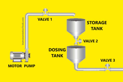
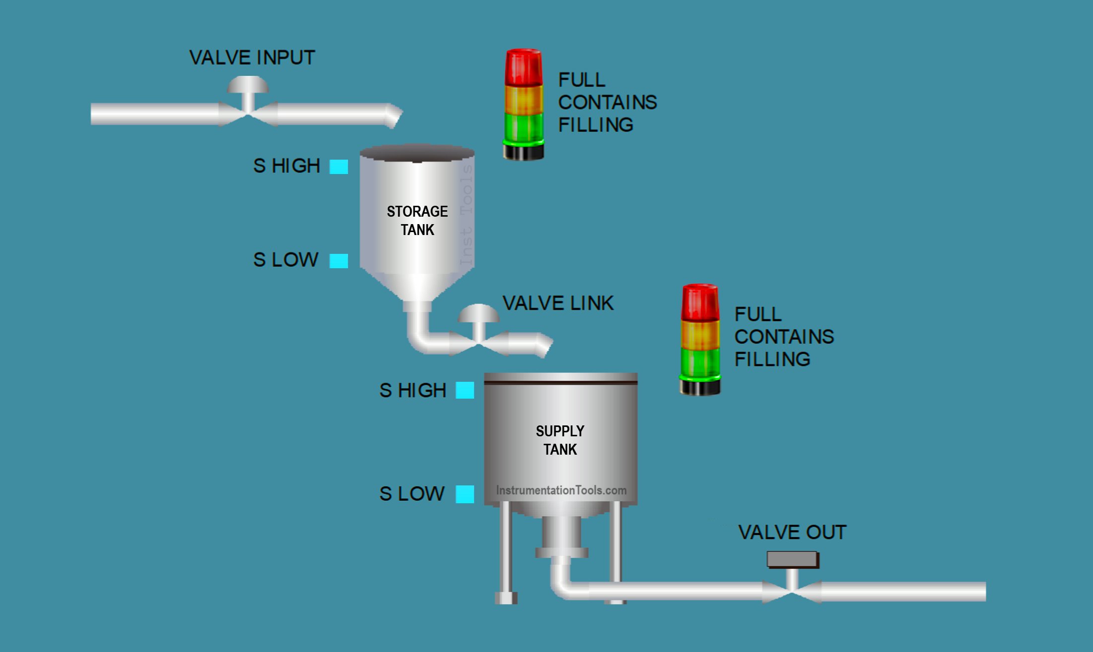
This article discusses an automatic liquid transfer between two tanks with a filling system using Siemens TIA Portal software, designed to control the flow of liquid automatically between a storage tank and a supply tank by maintaining the liquid levels within predefined minimum and maximum limits. The storage tank receives liquid from the main source, while the supply tank delivers the liquid to the next process. The system is designed with a filling priority for the storage tank to ensure a constant supply of liquid, and it is equipped with indicator lights to monitor the liquid levels in each tank in real time.
Program Objective
System Description:
The system consists of two tanks connected in series:
- Tank 1: Serves as the initial liquid storage tank.
- Tank 2: Functions as the feeder tank.
- Both tanks have defined minimum and maximum level limits that must be maintained.
- There is an input valve on Tank 1 and an output valve on Tank 2.
- A link valve is used to transfer liquid from Tank 1 to Tank 2.
System Operational Steps:
Filling Tank 1 (Storage Tank):
- The input valve opens when the liquid level in Tank 1 is below the maximum limit.
- When the input valve is open, the “Filling Tank 1” indicator turns on.
- The input valve closes when the liquid reaches the maximum level in Tank 1.
Transferring Liquid to Tank 2 (Feeder Tank):
The link valve between Tank 1 and Tank 2 opens if:
- The liquid level in Tank 2 is below the maximum limit, and
- The liquid level in Tank 1 is above the minimum limit (sufficient to transfer).
When this valve is open, the “Filling Tank 2” indicator turns on.
The valve closes if:
- Tank 2 reaches its maximum level, or
- Tank 1 falls below the minimum level.
Liquid Output from Tank 2:
Liquid is discharged manually through the output valve on Tank 2.
Tank Level Indicators:
For each tank:
- If both HIGH and LOW level sensors are active → the “Full” indicator lights up.
- If only the LOW level sensor is active → the “Contains” indicator lights up.
- If both HIGH and LOW level sensors are inactive → no indicator is on (tank is empty).
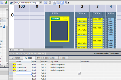
IO Mapping in TIA Portal
| S.No. | Comment | Input (I) | Output (Q) | Memory Bit |
|---|---|---|---|---|
| 1 | START | I0.0 | ||
| 2 | STOP | I0.1 | ||
| 3 | SENS_LOW_TANK1 | I0.2 | ||
| 4 | SENS_HIGH_TANK1 | I0.3 | ||
| 5 | SENS_LOW_TANK2 | I0.4 | ||
| 6 | SENS_HIGH_TANK2 | I0.5 | ||
| 7 | PB_VALVE_OUT | I0.6 | ||
| 8 | VALVE_INPUT | Q0.0 | ||
| 9 | VALVE_LINK | Q0.1 | ||
| 10 | VALVE_OUT | Q0.2 | ||
| 11 | TANK1_FILLING | Q0.3 | ||
| 12 | TANK1_FULL | Q0.4 | ||
| 13 | TANK1_CONTAINS | Q0.5 | ||
| 14 | TANK2_FILLING | Q0.6 | ||
| 15 | TANK2_FULL | Q0.7 | ||
| 16 | TANK2_CONTAINS | Q1.0 | ||
| 17 | SYSTEM_ON | M0.0 |
Liquid Transfer Between Two Tanks
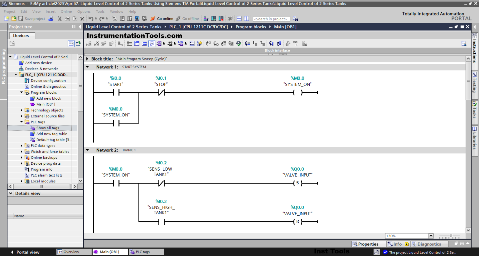
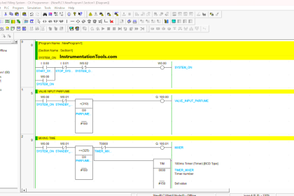
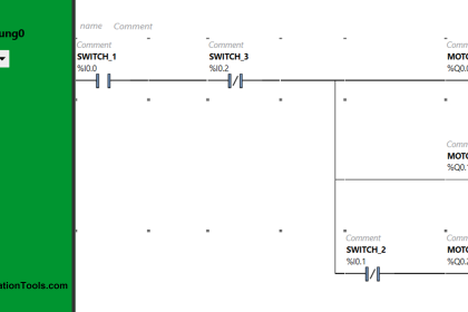
NETWORK 1 (START SYSTEM)
In this Network, the memory bit SYSTEM_ON(M0.0) will be in a HIGH state if the START (I0.0) button is pressed. The memory bit SYSTEM_ON(M0.0) will remain in a HIGH state even though the START (I0.0) button has been released. Because it uses Latching.
If the STOP (I0.1) button is pressed, then the memory bit SYSTEM_ON (M0.0) will be in a LOW state.
NETWORK 2 (TANK 1)
In this Network, the VALVE_INPUT (Q0.0) output will be OPEN if the NO contact of the memory bit SYSTEM_ON(M0.0) is in a HIGH state and the NC contact of the SENS_LOW_TANK1 (I0.2) sensor is in a LOW state.
Even though the NC contact of the SENS_LOW_TANK1 (I0.2) sensor is in the HIGH state, the VALVE_INPUT (Q0.0) output will remain OPEN. Because it uses the SET Output instruction.
The VALVE_INPUT (Q0.0) output will be CLOSED if the NO contact of the SENS_HIGH_TANK1 (I0.3) sensor is in the HIGH state. Because it uses the RESET Output instruction.
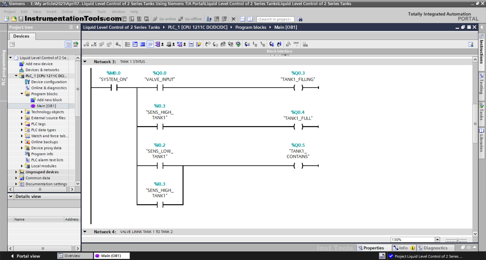
NETWORK 3 (TANK 1 STATUS)
In this Network, the TANK1_FILLING (Q0.3) output will be ON when the NO contact of the memory bit SYSTEM_ON(M0.0) and VALVE_INPUT(Q0.0) are in the HIGH state.
The TANK1_FULL (Q0.4) output will be ON when the NO contact of the SENS_HIGH_TANK1 (I0.3) sensor is in the HIGH state.
The TANK1_CONTAINS (Q0.5) output will be ON if the NO contact of the SENS_LOW_TANK1 (I0.2) or SENS_HIGH_TANK1 (I0.3) sensors is in the HIGH state.
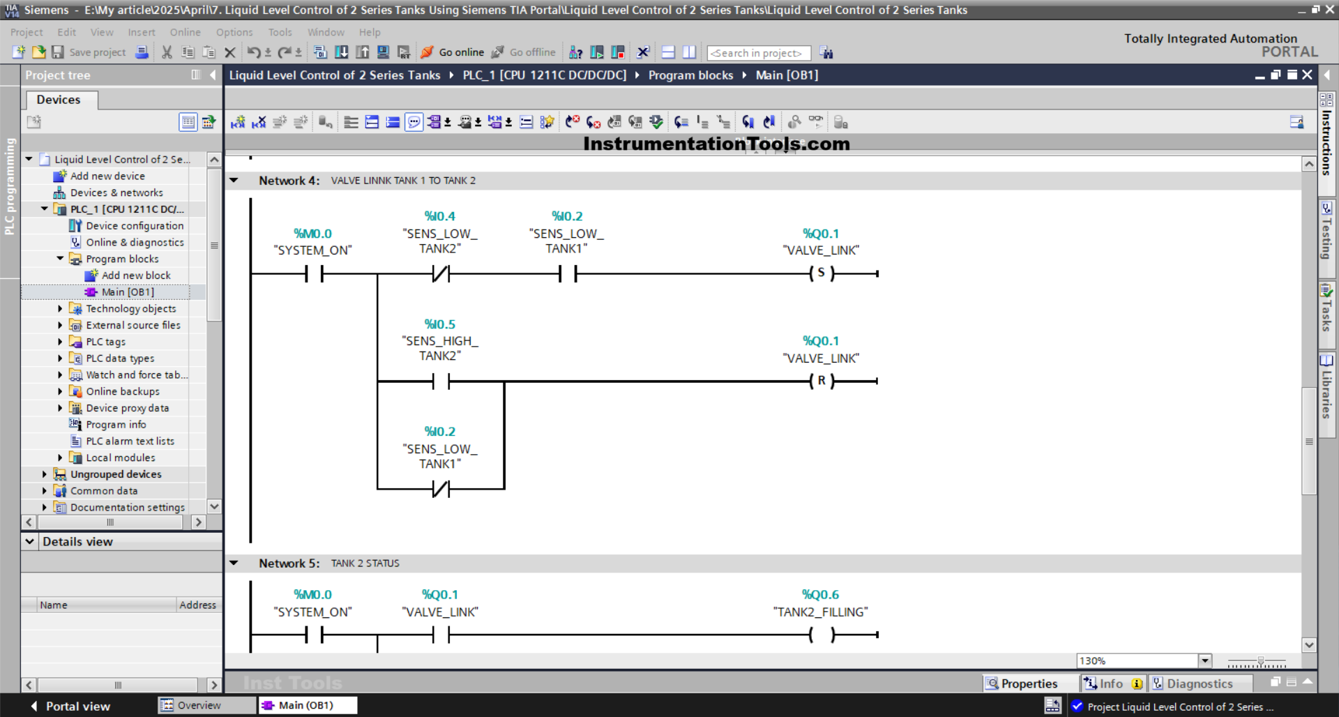
NETWORK 4 (VALVE LINK TANK 1 TO TANK 2)
In this Network, the VALVE_LINK (Q0.1) output will be OPEN if the NO contact of the memory bit SYSTEM_ON (M0.0) and the SENS_LOW_TANK1 (I0.2) sensor are in the HIGH state.
Even though the NC contact of the SENS_LOW_TANK2 (I0.4) sensor is in the HIGH state or the NO contact of the SENS_LOW_TANK1 (I0.2) sensor is in the LOW state, the VALVE_LINK (Q0.1) output will remain OPEN. Because it uses the SET Output instruction.
If the NO contact of the SENS_HIGH_TANK2 (I0.5) sensor is in the HIGH state or the NC contact of the SENS_LOW_TANK1 (I0.2) sensor is in the LOW state, then the VALVE_LINK (Q0.1) output will be CLOSE. Because it uses the RESET Output instruction.
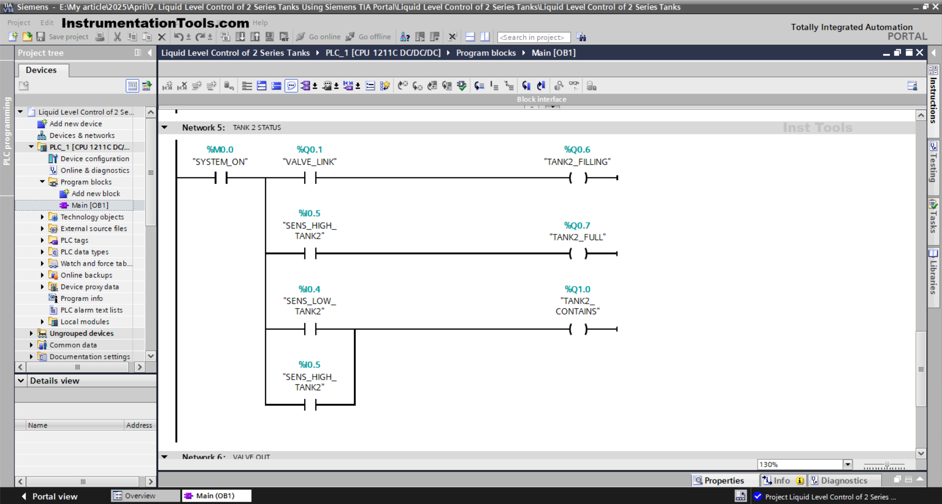
NETWORK 5 (TANK 2 STATUS)
The TANK2_FILLING (Q0.6) output will be ON when the NO contact of the memory bit SYSTEM_ON (M0.0) and VALVE_LINK (Q0.1) are in the HIGH state.
The TANK2_FULL (Q0.7) output will be ON when the NO contact of the SENS_HIGH_TANK2 (I0.5) sensor is in the HIGH state.
The TANK2_CONTAINS (101.01) output will be ON if the NO contact of the SENS_LOW_TANK2 (I0.4) or SENS_HIGH_TANK2 (I0.5) sensors is in the HIGH state.
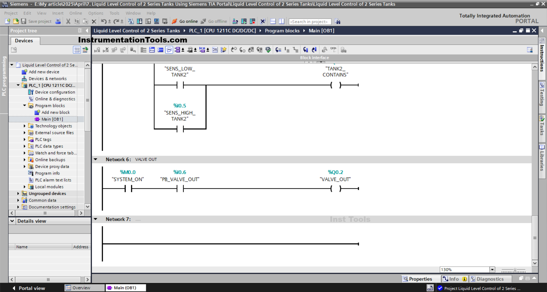
NETWORK 6 (VALVE OUT)
In this Network, the VALVE_OUT (Q0.2) output will be OPEN when the NO contact of the memory bit SYSTEM_ON (M0.0) is in the HIGH state and the PB_VALVE_OUT (I0.6) button is pressed.
Read Next:
- Siemens STEP 7 PLC for Liquid Level Alarm and Control
- SIMATIC PLC Programming for Aquaculture System
- Vehicle Washing PLC Project: Spray, Brush, Rinse, Dry
- SIMATIC Program for Product Sorting and Heating Process
- Automated Waste Sorting System Using PLC Program