Do you know about Loop Check of 4-20mA or HART Transmitters or Instruments Loop check procedure ? This article provides the basic info about loop checks of field instruments.
Loop Check of 4-20mA or HART Transmitters
There are two ways to loop check a 4-20 mA/HART transmitter current loop:
- Inject physical sensor input
- Force output current
A third way would be to use a loop checker tool in place of the 4-20 mA/HART transmitter to inject a current from the field-end to verify the reading in the control system end. However, the voltage drop of a loop checker is different from that of a 4-20 mA/HART transmitter so the result may be misleading.
Inject Physical Sensor Input
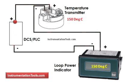
Inject the actual physical input on the 4-20 mA/HART transmitter such as pumping up physical pressure on a pressure transmitter, inject a simulated temperature sensor signal from a calibrator on a temperature transmitter, or put the temperature sensor in a temperature bath.
As this is done in 5 points; first at 0%, then 25%, 50%, 75%, and 100% in each step of the test, the engineering unit reading in the control system end is verified. This is very time consuming as the sensor has to be disconnected or isolated and the signal injection connected.
This requires one person in the field with a calibrator to inject the input and a second person in the control room to verify the reading on the control system screen. Ideally also simulate a sensor failure, such as by disconnecting the sensor cable (not the transmitter wires), to verify correct NAMUR NE43 failure alarm indication in the control system.
Also Read : Basics of Loop Checks
This loop check method has the advantage that it verifies that sensor is working, that the transmitter signal is marshaled to the correct input card channel, and that the 4-20 mA range setting in the transmitter is matching control system range setting which is critical.
A multi-meter can also be inserted in the loop as an additional check.
If the 4-20 mA transmitter or system does not support HART, this is the only way.
Force Output Current
Another way is to force the output current of the 4-20 mA/HART transmitter irrespective of applied input. This HART function is known as “loop test”. A person in the field can use a handheld field communicator to force the current first to 4 mA, then 8 mA, 12 mA, 16 mA, and 20 mA in each step of the test.
Ideally also test < 3.6 mA and >21 mA to verify correct NAMUR NE43 failure alarm indication in the control system. If the 4-20 mA/HART transmitter has a local display it may be possible to force the output current from the local operator interface without using a handheld field communicator. By loop checking from the field it is verified that the transmitter signal is marshaled to the correct input card channel.
If the plant has an Intelligent Device Management (IDM) software part of the Asset Management System (AMS) the technician can instead force the output from an indoor workstation without having to go to the field. A second technician verifies the reading on the control system is correct.
Note that the reading cannot be verified from the IDM software because the IDM software looks at the reading from the transmitter-end, not the 4-20 mA current received in the controller which is what matters in a current loop check.
By loop checking from the IDM software, a transmitter signal marshaled to the wrong input card channel may not be detected. Therefore the correct device type should be verified separately.
Also Read : What is Loop Checks ?
The advantage of the current forcing method is that it does not require physical sensor input to be injected and which therefore is much faster. However, it does not verify that the range in the 4-20 mA/HART transmitter matches the range in the control system. Therefore the range should be verified separately.
After the loop check has been completed a plausibility check based on the prevailing condition should be made; such as ambient temperature, atmospheric pressure, empty tank, or no flow etc.
This verifies the sensor is working and also verifies that the loop test function has been exited properly and that the reading in the control system reflects actual physical input.
A multi-meter can also be inserted in the loop as an additional check
Note that the value in the display of the device is the measured process value, not the value corresponding to the forced current output.
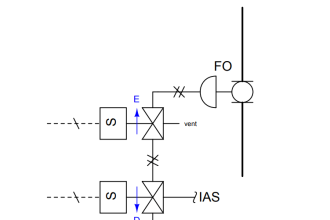
Control Valves Loop Checking (4-20 mA/HART)
There are three ways to loop check a 4-20 mA/HART based control valve positioner current loop:
- Watch the valve move
- Read position feedback
- Read-back loop current
In all of these approaches the control loop is put in manual and the control system output set to first 0%, then 25%, 50%, 75%, and 100% in each step of the test. The difference is in how the instrument technician verifies that the correct signal has been received in the 4-20 mA/HART valve positioner.
A fourth way would be to use a multi-meter in place of the 4-20 mA/HART valve positioner to measure the current in the field-end to verify it matches what is sent from the control system end.
However, the voltage drop of a multimeter is much lower than a 4-20 mA/HART valve positioner so the result may be misleading.
Observe Valve Movement
The operator at the control system puts the control loop in manual and sets the control system output first to 0%, then 25%, 50%, 75%, and 100% for each step of test, a second person in the field observes the actual valve movement.
This loop check method has the advantage that it verifies that the valve strokes over the full range and its movement is not limited. A multi-meter can also be inserted in the loop as an additional checks. If the 4-20 mA positioner or system does not support HART, this is the only way.
Read Position Feedback
The operator at the control system puts the control loop in manual and sets the control system output first to 0%, then 25%, 50%, 75%, and 100% for each step of test, a second person uses the IDM software to read the valve position feedback from the valve positioner.
This loop check method has the advantage that there is no need for a person to go to the field.
Read-back Loop Current
The operator at the control system puts the control loop in manual and sets the control system output first to 0%, then 25%, 50%, 75%, and 100% for each step of test, a second person uses the IDM software to read the loop current as received by the 4-20 mA/HART valve positioner.
This loop check method also does not require a person to go to the field. However, there is no indication if the valve is actually moving.
General Loop Checks Procedure
Steps in a loop check for a 4-20 mA/HART transmitter may include:
- Instruct operations to put the associated control loop in manual so control is not upset when PV changes when a new value is forced
- Instruct technician to select a test point (4mA,8mA,12mA & 20mA or applied 0 to 100% Physical Input)
- Instruct the technician to tell the person at the control system to note down the system reading for this test point
- Repeat the above two steps for different test points (4mA,8mA,12mA & 20mA or applied 0 to 100% Physical Input)
- Instruct the technician to return the device to normal operation if loop check is completed
- Instruct operations the associated control loop can be put back in automatic
Reference : Eddl.org
If you liked this article, then please subscribe to our YouTube Channel for PLC and SCADA video tutorials.
You can also follow us on Facebook and Twitter to receive daily updates.
Read Next:


Very useful info sir. Salute u.
Very Good web site i like that
Thank You very Much for Sharing these knowledge.
thanks
Thanks for your concern for people to know what you know.
Thanks for not hiding knowledge!
Excellent
Como é bom estudar , e aprender com pessoas , que gosta de passar conhecimento.
Translated – How to study, and learn with people, who like to pass with knowledge.