This article will discuss the system for regulating the speed of escalators that operate automatically using the Siemens PLC. The purpose of this system is to control the movement of the escalator automatically based on the number of detected users. The system is equipped with multiple speed levels that will adjust accordingly; the more users there are, the lower the speed. This allows for energy savings by activating the escalator only when needed. The system also features an emergency stop function to ensure the safety and security of users.
Program Objective
System Steps:
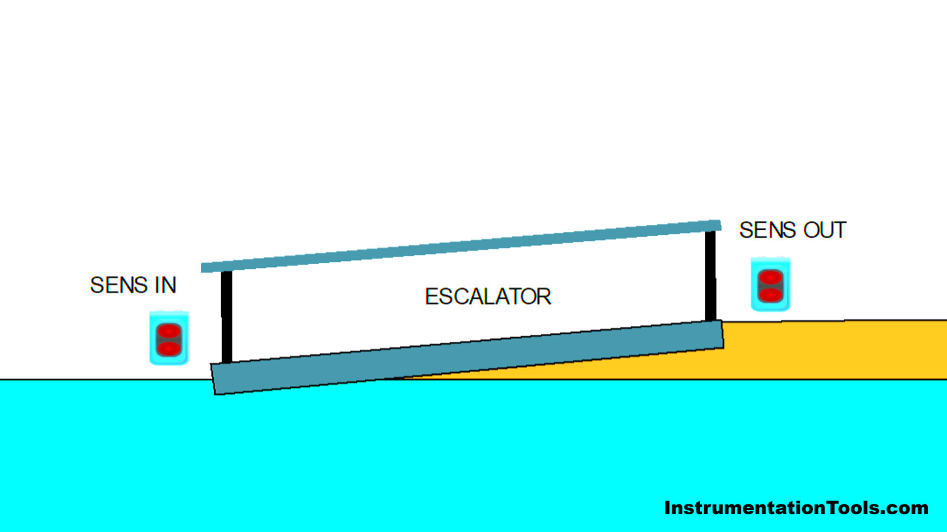
User Detection:
The proximity sensor will detect the presence of objects approaching the escalator and those who have exited the escalator.
Escalator Activation:
The speed of the escalator will decrease as the number of users increases for safety reasons.
The escalator has three speed levels:
- No users → The escalator stops.
- 1-5 users → The escalator moves at a speed of 12 km/h.
- 6-9 users → The escalator moves at a speed of 8 km/h.
- 10-14 users → The escalator moves at a speed of 5 km/h.
Automatic Shutdown:
- If the sensor does not detect the presence of users, the motor will stop to save energy.
- If users are detected again, the system will automatically turn on.
Safety Features:
- The Emergency Stop Button is used to stop the escalator in case of an emergency.
- A Fault Alarm will sound when the Emergency Button is activated.
Inputs and Outputs Mapping Details
| S.No. | Comment | Input (I) | Output(Q) | Memory Words | Memory Bit |
| 1 | PB_START | I0.0 | |||
| 2 | PB_STOP | I0.1 | |||
| 3 | SENS_IN | I0.2 | |||
| 4 | SENS_OUT | I0.3 | |||
| 5 | EMERGENCY | I0.4 | |||
| 6 | MOTOR | Q0.0 | |||
| 7 | LAMP_EMERGENCY | Q0.1 | |||
| 8 | TEMP_PEOPLE | MW2 | |||
| 9 | SPEED_MOTOR | MW4 | |||
| 10 | SYSTEM_ON | M0.0 | |||
| 11 | IR_MOTOR1 | M0.1 | |||
| 12 | IR_MOTOR2 | M0.2 | |||
| 13 | IR_MOTOR3 | M0.3 | |||
| 14 | TEMP_SENS_IN | M0.4 | |||
| 15 | TEMP_SENS_OUT | M0.5 |
Escalator Speed Control PLC Logic
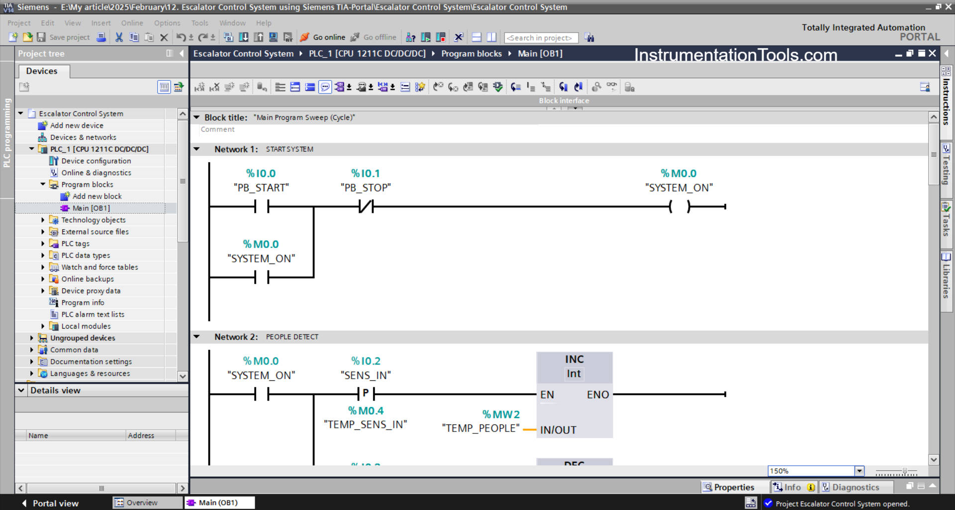
NETWORK 1 (START SYSTEM)
In this network, the memory bit SYSTEM_ON (M0.0) will be in the HIGH state when the PB_START (I0.0) button is Pressed. Because it uses Latching, even though the PB_START (I0.0) button has been Released the memory bit SYSTEM_ON (M0.0) will remain in the HIGH state.
If the PB_STOP (I0.1) button has been Pressed, the memory bit SYSTEM_ON (M0.0) becomes in the LOW state.
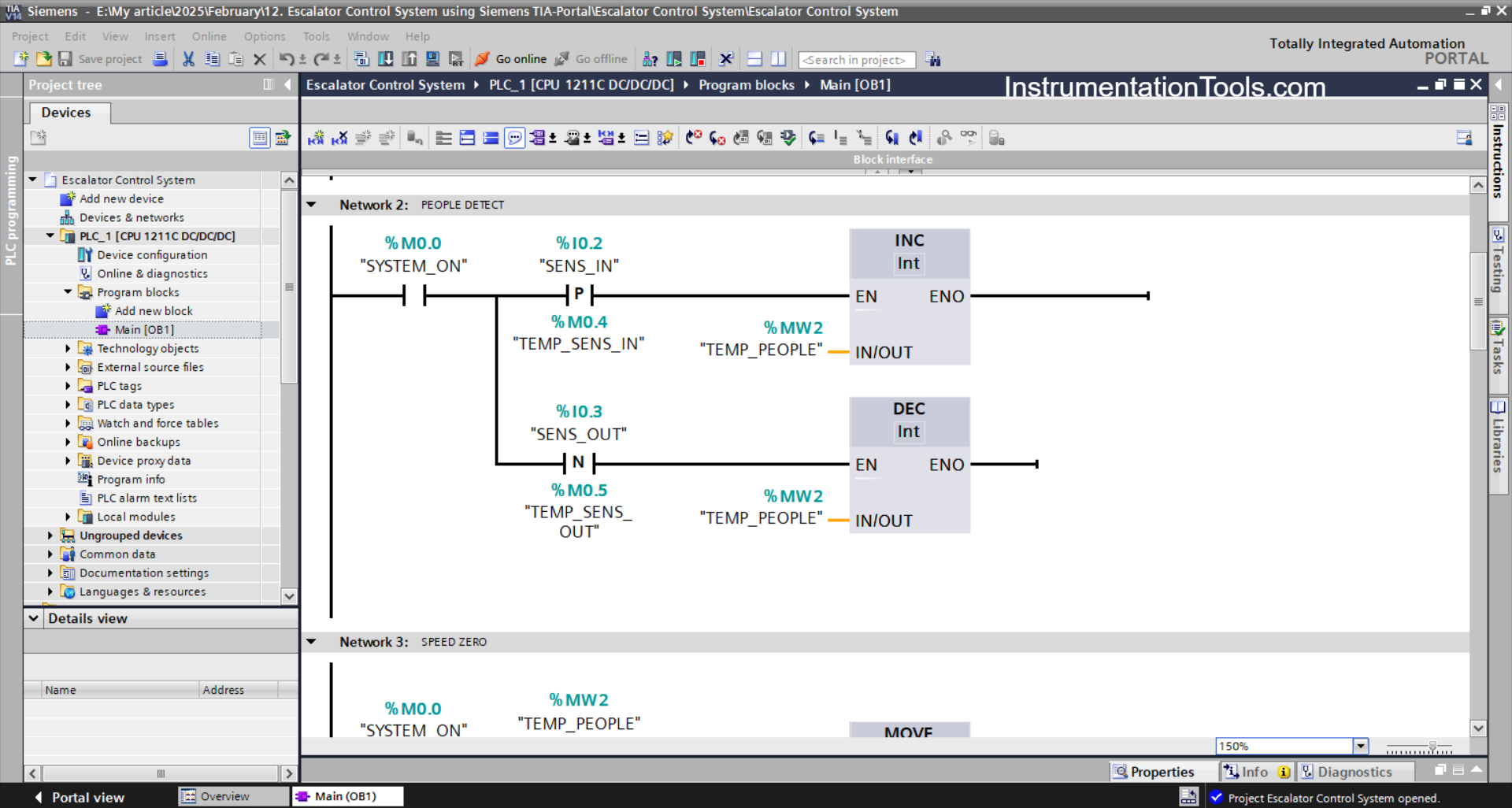
NETWORK 2 (PEOPLE DETECT)
In this network, because it uses the INCREMENT instruction, the value in the memory word TEMP_PEOPLE (MW2) will increase (+1) if the NO contact of the memory bit SYSTEM_ON (M0.0) and the SENS_IN (I0.2) sensor are in the HIGH state.
And, the value in the memory word TEMP_PEOPLE (MW2) will decrease (-1) when the NO contact of the memory bit SYSTEM_ON (M0.0) and the SENS_OUT (I0.3) sensor are in the HIGH state. Because it uses the DECREMENT instruction.
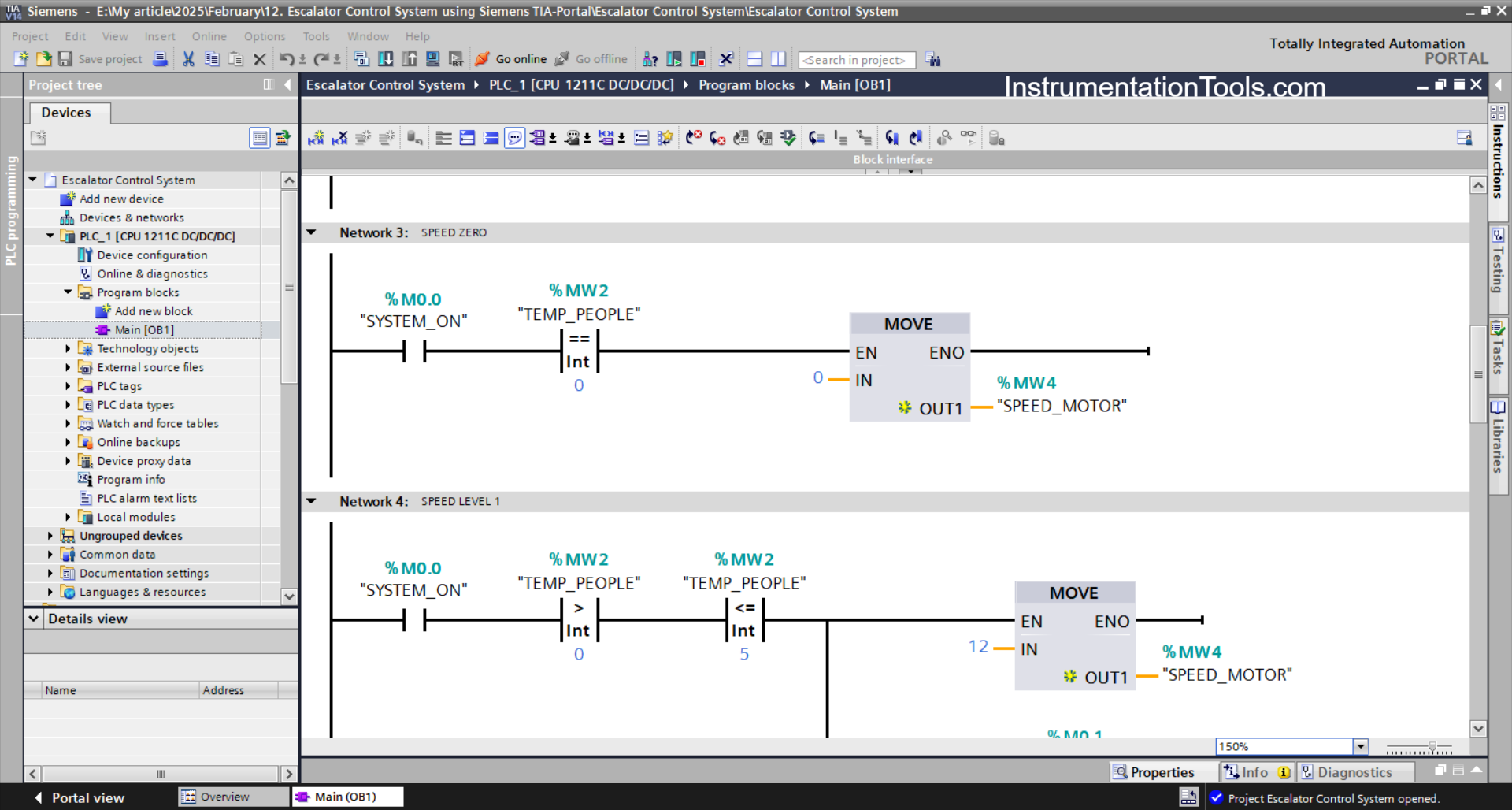
NETWORK 3 (SPEED ZERO)
In this network, the memory word SPEED_MOTOR (MW4) will have a value of zero “0” if the NO contact of the memory bit SYSTEM_ON (M0.0 in the HIGH state and the value in the memory word TEMP_PEOPLE (MW2) is Equal to zero “0”.
The MOV instruction moves the zero value “0” to the memory word SPEED_MOTOR (MW4).
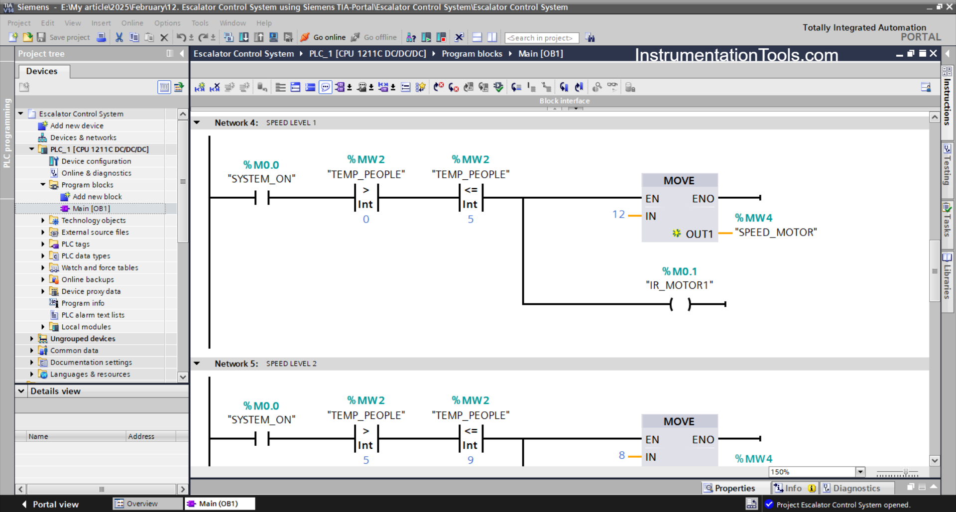
NETWORK 4 (SPEED LEVEL 1)
In this network, the memory bit IR_MOTOR1 (M0.1) will be in the HIGH state and the memory word SPEED_MOTOR (MW4) will have the value “12” when the NO contact of the memory bit SYSTEM_ON (M0.0) in the HIGH state and the value in the memory word TEMP_PEOPLE (MW2) is Greater Than “0” and Less Than or Equal to “5”.
The MOV instruction will move the value “12” to the memory word SPEED_MOTOR (MW4).
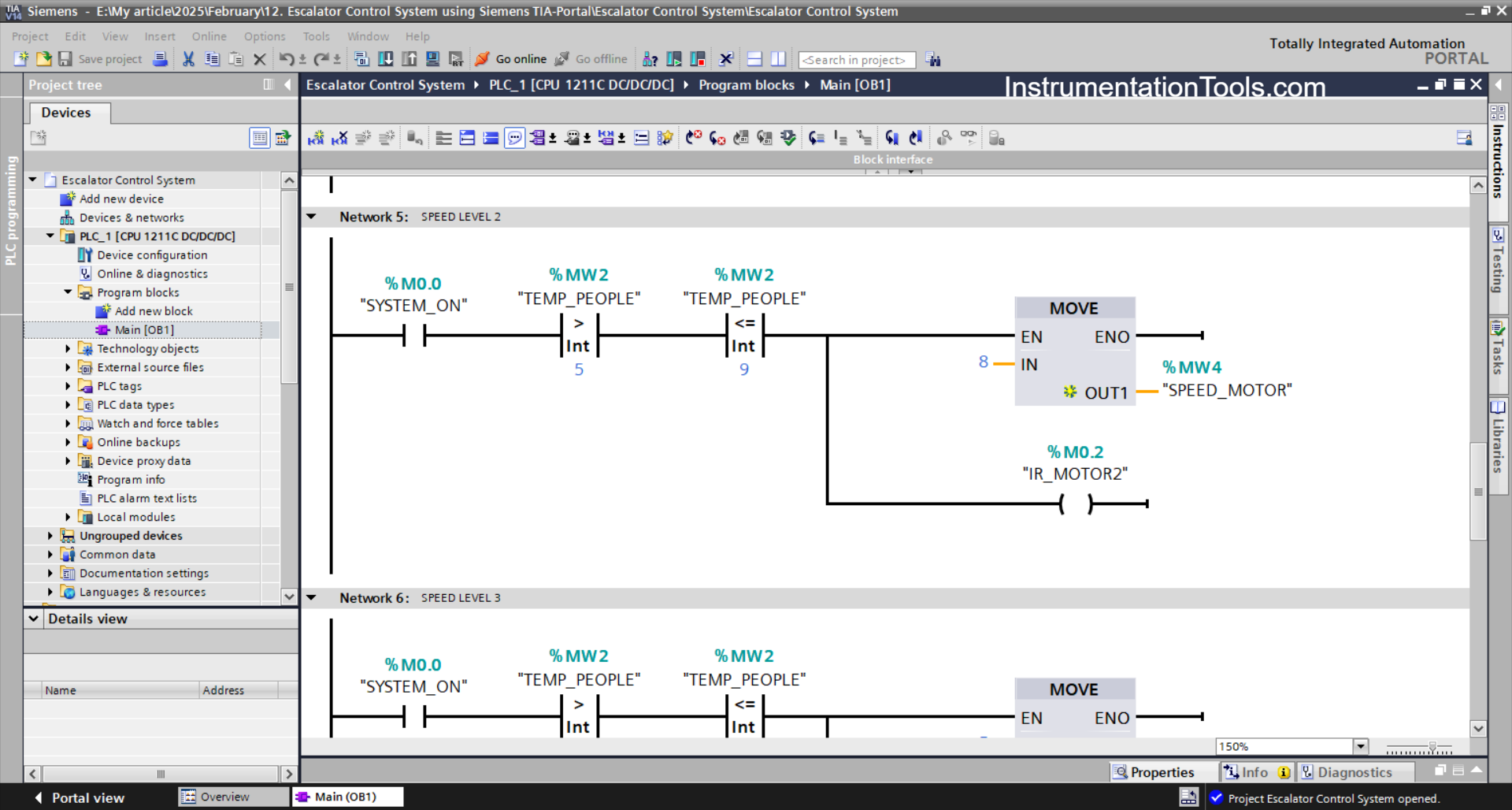
NETWORK 5 (SPEED LEVEL 2)
In this Network, the memory bit IR_MOTOR2 (M0.2) will be in the HIGH state and the memory word SPEED_MOTOR (MW4) will have the value “8” when the NO contact of the memory bit SYSTEM_ON (M0.0) in the HIGH state and the value in the memory word TEMP_PEOPLE (MW2) is Greater Than “5” and Less Than or Equal to “9”.
The MOV instruction will move the value “8” to the memory word SPEED_MOTOR (MW4).
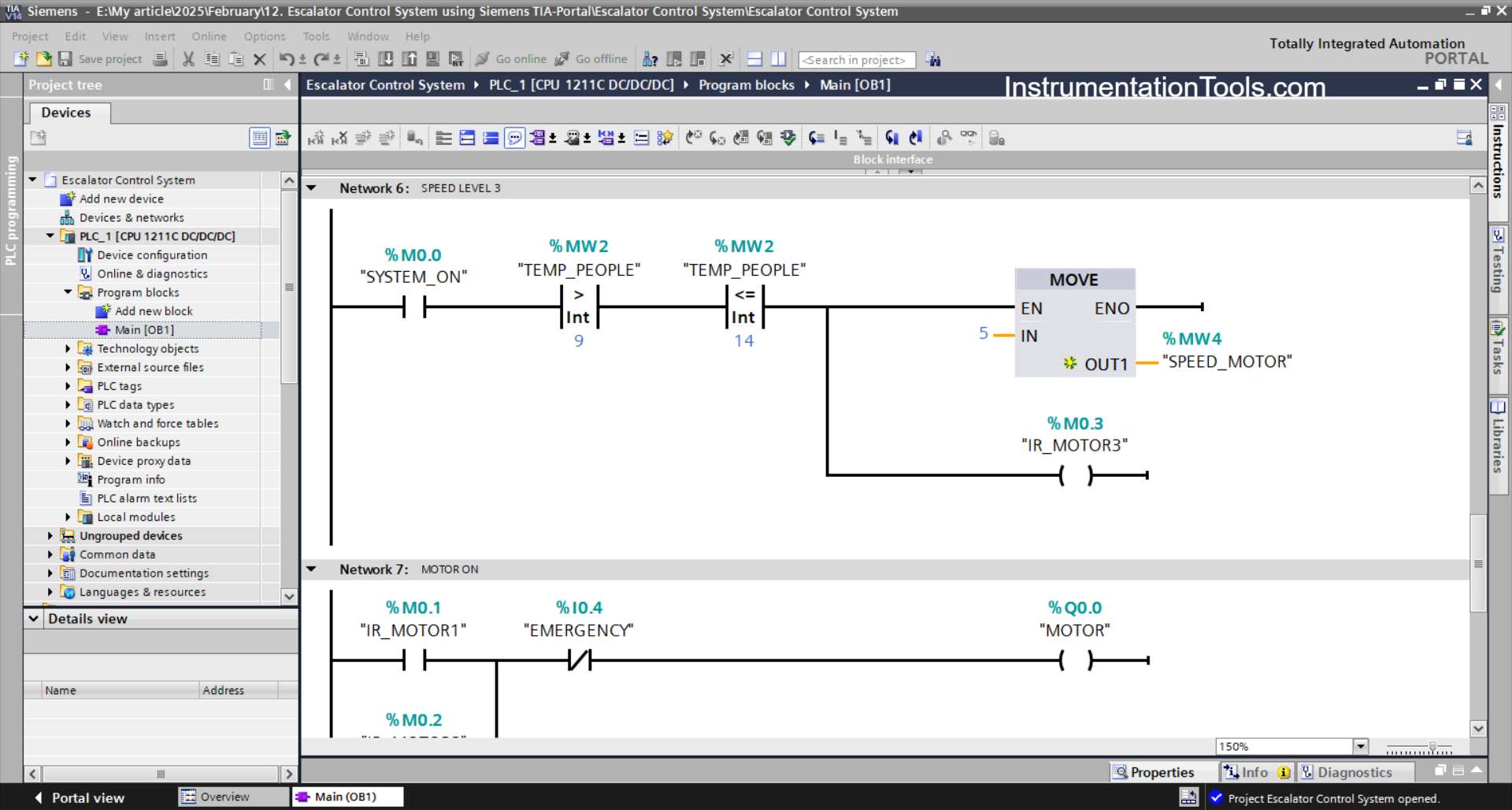
NETWORK 6 (SPEED LEVEL 3)
In this Network, the memory bit IR_MOTOR3 (M0.3) will be in the HIGH state and the value in the memory word SPEED_MOTOR (MW4) will be “5” when the NO contact of the memory bit SYSTEM_ON (M0.0) in the HIGH state and the value in the memory word TEMP_PEOPLE (MW2) is Greater Than “9” and Less Than or Equal to “14”.
The MOV instruction will move the value “5” to the memory word SPEED_MOTOR (MW4).
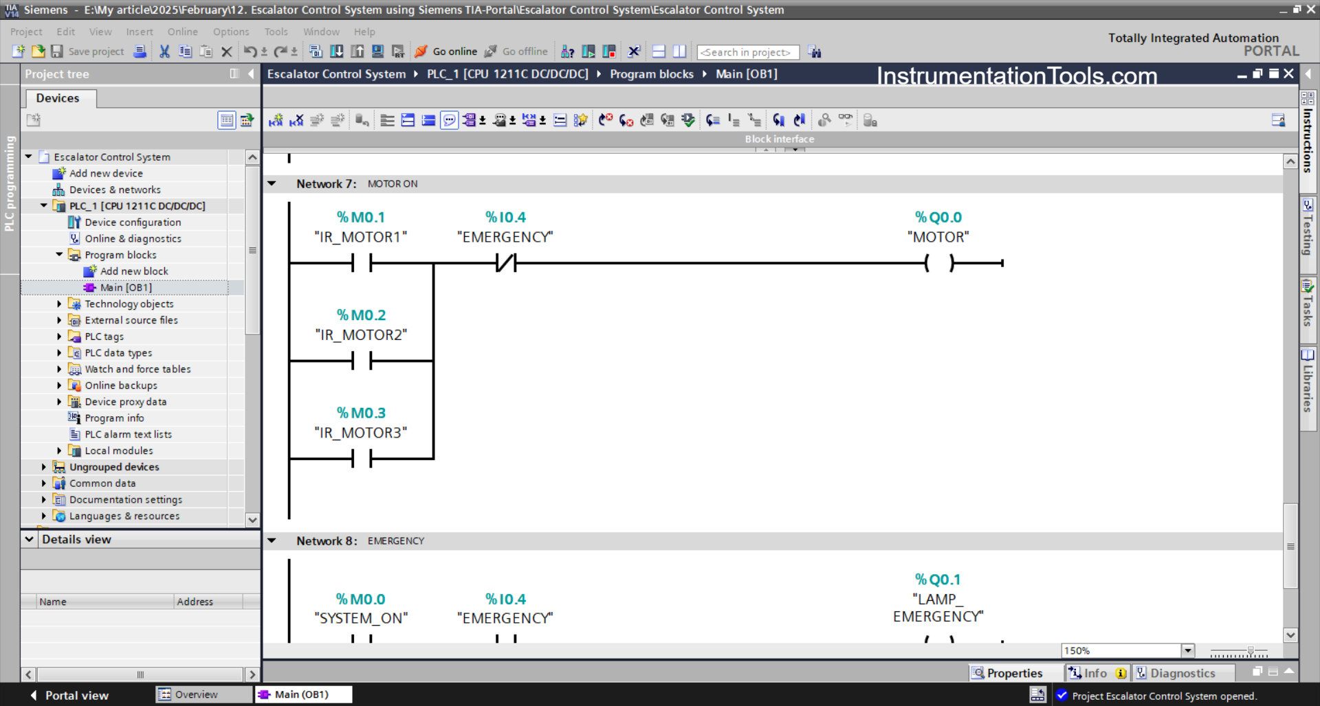
NETWORK 7 (MOTOR ON)
In this network, the MOTOR (Q0.0) output will be ON if the NO contact of any of the memory bits IR_MOTOR1 (M0.1), IR_MOTOR2 (M0.2), or IR_MOTOR3 (M0.3) is in the HIGH state.
The MOTOR (Q0.0) output will be OFF when the EMERGENCY (I0.4) button is Pressed.
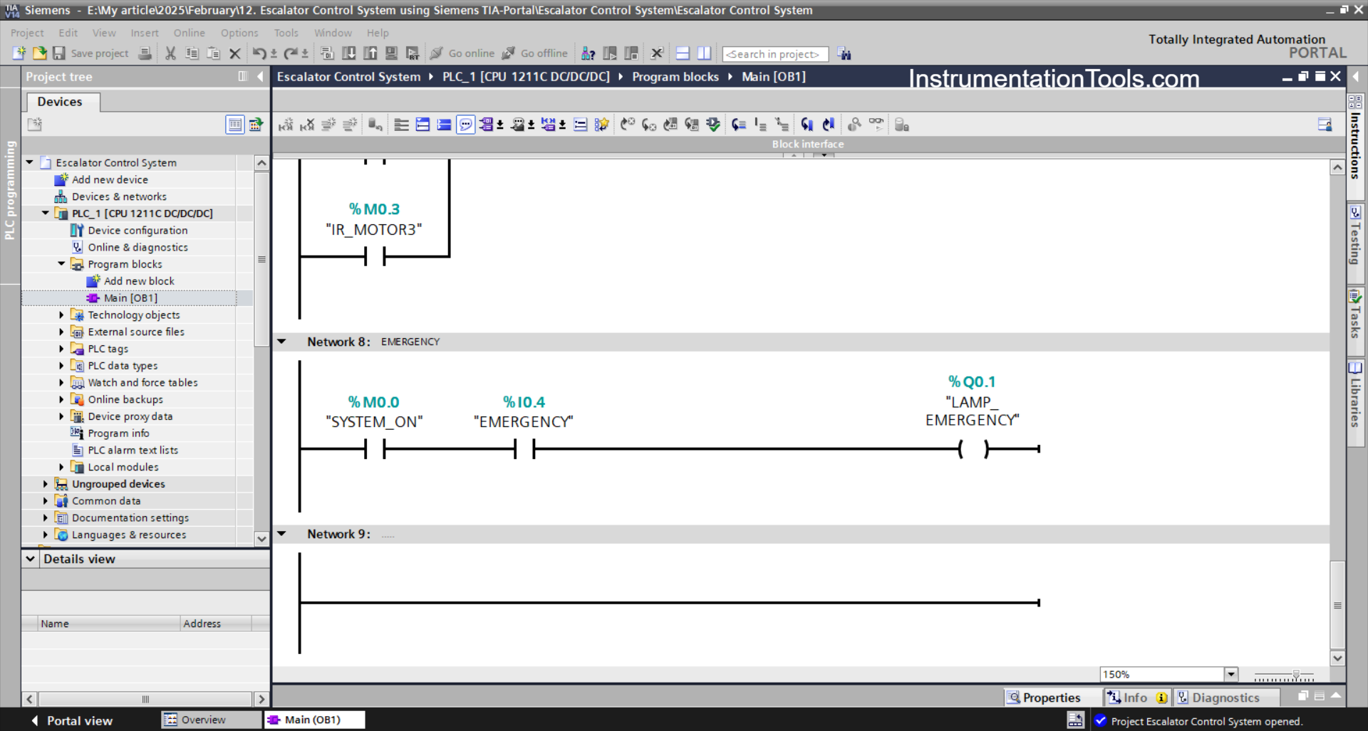
NETWORK 8 (EMERGENCY)
In this Network, the LAMP_EMERGENCY (Q0.1) output will be ON when the EMERGENCY (I0.4) button is Pressed.
Read Next:
- Motor Reverse and Forward Direction Logic
- Program for Light Sequences using Timers
- Can a PLC Function Without an HMI or SCADA
- PLC Programming for Weight-Based Packaging
- Traffic Light Sequence using Functional Blocks