Inst ToolsInst ToolsInst Tools
  • Courses
  • Automation
    • PLC
    • Control System
    • Safety System
    • Communication
    • Fire & Gas System
  • Instrumentation
    • Design
    • Pressure
    • Temperature
    • Flow
    • Level
    • Vibration
    • Analyzer
    • Control Valve
    • Switch
    • Calibration
    • Erection & Commissioning
  • Interview
    • Instrumentation
    • Electrical
    • Electronics
    • Practical
  • Q&A
    • Instrumentation
    • Control System
    • Electrical
    • Electronics
    • Analog Electronics
    • Digital Electronics
    • Power Electronics
    • Microprocessor
Search
  • Books
  • Software
  • Projects
  • Process
  • Tools
  • Basics
  • Formula
  • Power Plant
  • Root Cause Analysis
  • Electrical Basics
  • Animation
  • Standards
  • 4-20 mA Course
  • Siemens PLC Course
Reading: PLC Hoist Crane Programming: Example using Schneider
Share
Notification Show More
Font ResizerAa
Inst ToolsInst Tools
Font ResizerAa
  • Courses
  • Design
  • PLC
  • Interview
  • Control System
Search
  • Courses
  • Automation
    • PLC
    • Control System
    • Safety System
    • Communication
    • Fire & Gas System
  • Instrumentation
    • Design
    • Pressure
    • Temperature
    • Flow
    • Level
    • Vibration
    • Analyzer
    • Control Valve
    • Switch
    • Calibration
    • Erection & Commissioning
  • Interview
    • Instrumentation
    • Electrical
    • Electronics
    • Practical
  • Q&A
    • Instrumentation
    • Control System
    • Electrical
    • Electronics
    • Analog Electronics
    • Digital Electronics
    • Power Electronics
    • Microprocessor
Follow US
All rights reserved. Reproduction in whole or in part without written permission is prohibited.
Inst Tools > Blog > PLC Tutorials > PLC Hoist Crane Programming: Example using Schneider

PLC Hoist Crane Programming: Example using Schneider

Learn PLC hoist crane programming with a practical example using Schneider EcoStruxure Machine Expert to improve your automation skills.

Last updated: October 21, 2024 8:37 pm
Editorial Staff
PLC Tutorials
No Comments
Share
7 Min Read
SHARE

This article discusses the PLC program to control Crane movement using the Schneider PLC in the Ecostruxure Machine Expert-Basic software. The Crane Machine has a Trolley that can move Left or Right and a Hoist that can move Up or Down. This PLC system uses a Proximity Sensor to limit the range of Left or Right movement of the Trolley and Upward movement of the Hoist Crane. This system has an Emergency button to Stop all Crane movements without turning Off the system.

Contents
PLC Hoist Crane ProgrammingI/O AddressingSchneider Programming of PLC

PLC Hoist Crane Programming

This PLC program has 7 buttons:

  1. START SYSTEM (I0.0) button is used to turn ON the system.
  2. The STOP SYSTEM (I0.1) button is used to turn OFF the system.
  3. UP_BUTTON (I0.5) is used to move the Hoist Crane UP. When this button is Pressed, the Output OUT_UP (Q0.3) will be ON.
  4. DOWN_BUTTON (I0.4) button is used to move the Hoist Crane DOWN. When this button is Pressed, the output OUT_DOWN (Q0.2) will be ON.
  5. LEFT_BUTTON (I0.2) is used to move the Crane to the LEFT. When this button is Pressed, the output OUT_LEFT (Q0.0) will be ON.
  6. The RIGHT_BUTTON (I0.3) button is used to move the Crane to the RIGHT. When this button is Pressed, then the output OUT_RIGHT (Q0.1) will be ON.
  7. EMERGENCY (I0.6) button is used to Stop all Crane movement without turning OFF the system.

This Crane system uses a Proximity Sensor as a safety measure to prevent the Crane from moving beyond the safety limit.

  1. SENS_UP (I0.7) is used to limit the Highest position of the Hoist Crane, preventing the Hoist Crane from hitting the Hoist Motor.
  2. SENS_LEFT (I0.8) is used to limit the crane’s range when moving to the LEFT.
  3. SENS_RIGHT (I0.9) is used to limit the crane’s range when moving to the RIGHT.
Hoist Crane Automation with Schneider PLC
Crane PLC Programming

I/O Addressing

CommentInput (I)Output(Q)Memory Bits
START_SYSTEMI0.0  
STOP_SYSTEMI0.1  
LEFT_BUTTONI0.2  
RIGHT_BUTTONI0.3  
DOWN_BUTTONI0.4  
UP_BUTTONI0.5  
EMERGENCYI0.6  
SENS_LEFTI0.8  
SENS_RIGHTI0.9  
SENS_UPI0.7  
OUT_LEFT Q0.0 
OUT_RIGHT Q0.1 
OUT_DOWN Q0.2 
OUT_UP Q0.3 
SYSTEM_ON  M0
IR_LEFT  M1
IR_RIGHT  M2
IR_DOWN  M3
IR_UP  M4

Schneider Programming of PLC

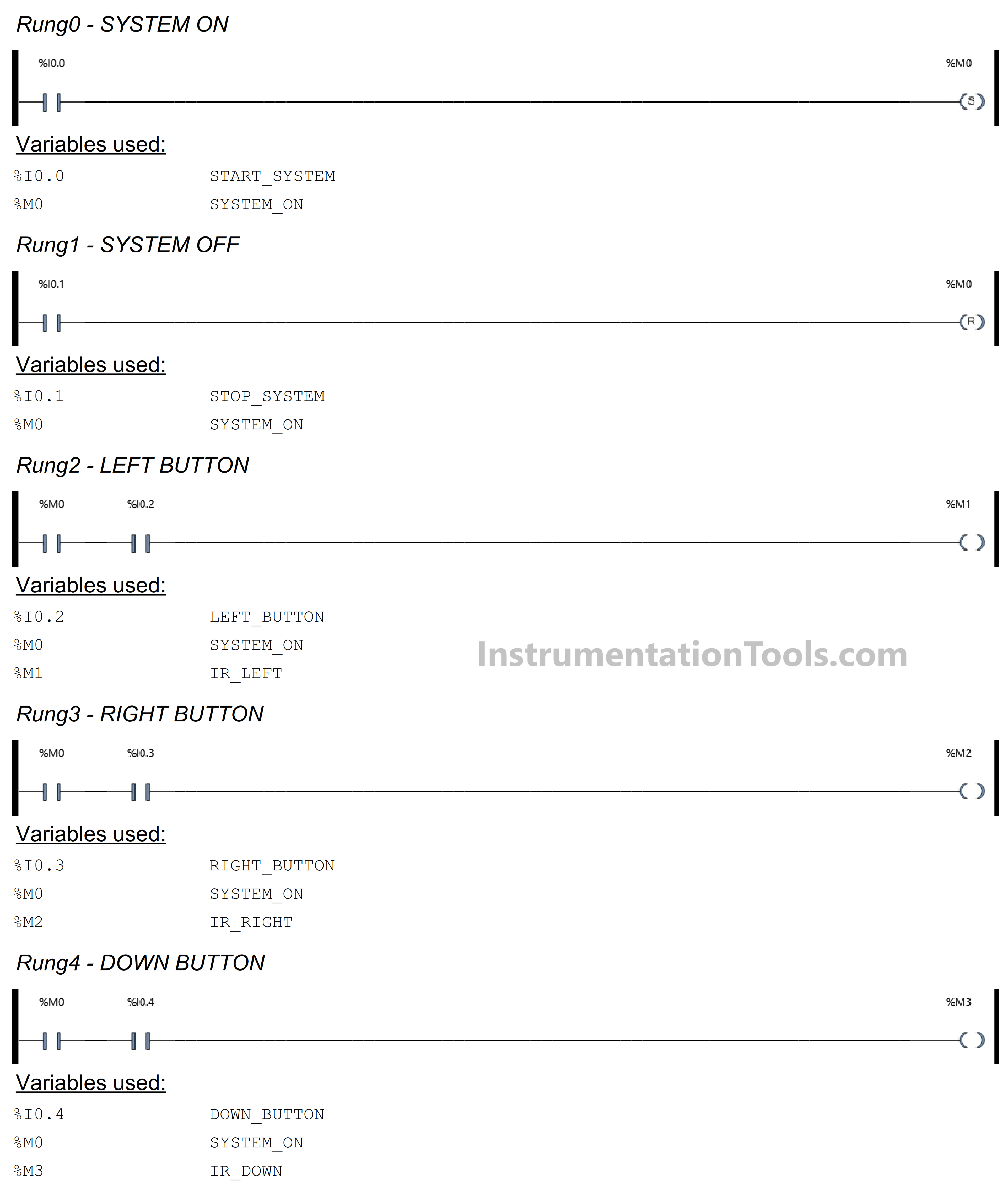
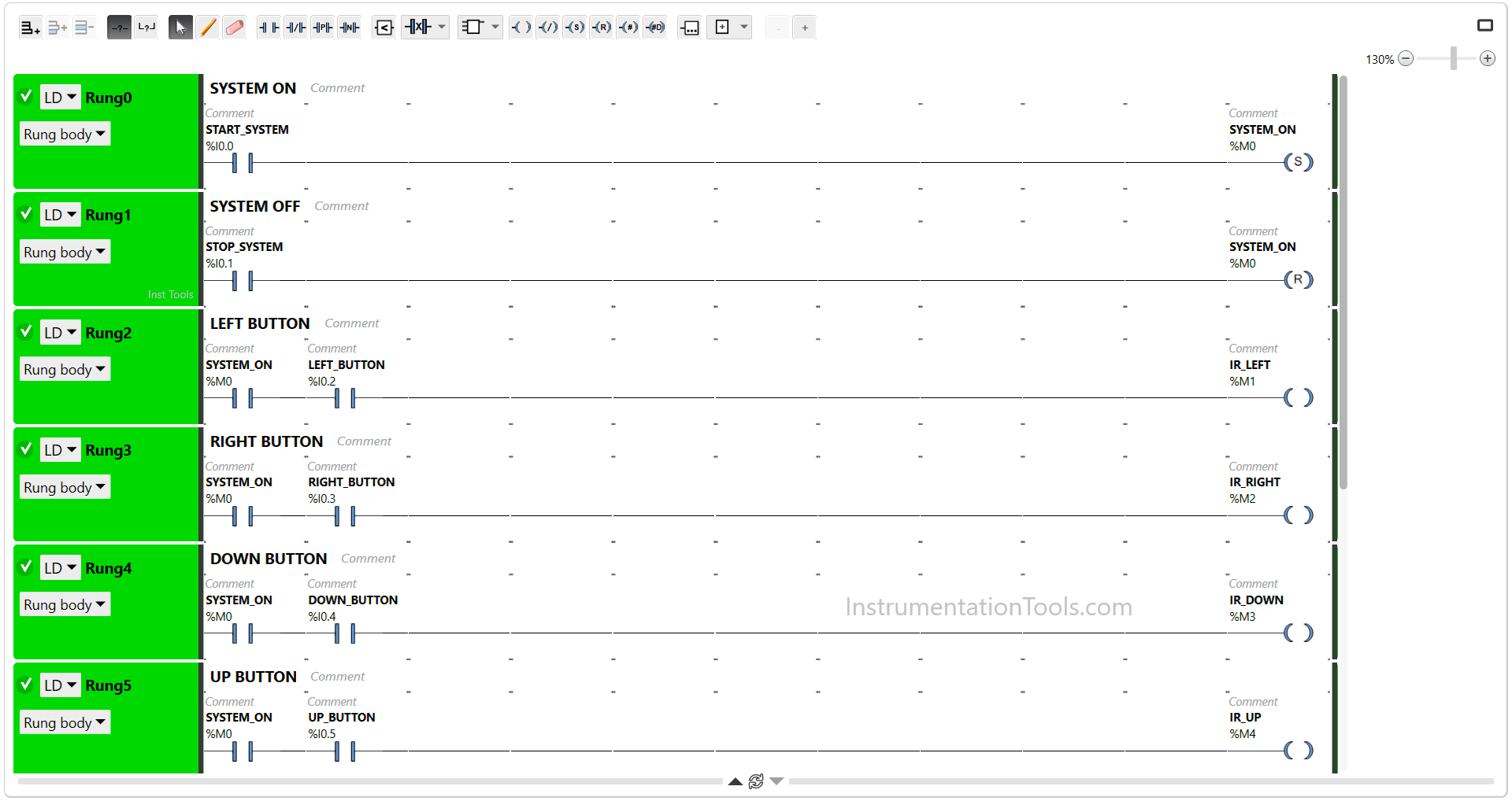
In this Rung, the memory bit SYSTEM_ON (M0) will be in the HIGH state if the START_SYSTEM (I0.0) button is Pressed. Because it uses the SET Coil Instruction, the memory bit SYSTEM_ON (M0) remains in the HIGH state even though the START_SYSTEM (I0.0) button has been Released.
PLC Hoist Crane Programming

RUNG 1 (SYSTEM OFF)

In this Rung, the memory bit SYSTEM_ON (M0) will become LOW state if the STOP_SYSTEM (I0.1) button is Pressed. Because it uses the RESET Coil Instruction.

RUNG 2 (LEFT BUTTON)

In this Rung, the memory bit IR_LEFT (M1) will be in the HIGH state if the NO contact of memory bit SYSTEM_ON (M0) in the HIGH state and the LEFT_BUTTON (I0.2) button is Pressed.

RUNG 3 (RIGHT BUTTON)

In this Rung, the memory bit IR_RIGHT (M2) will be in the HIGH state if the NO contact of memory bit SYSTEM_ON (M0) in the HIGH state and the RIGHT_BUTTON (I0.3) button is Pressed.

RUNG 4 (DOWN BUTTON)

In this Rung, the memory bit IR_DOWN (M3) will be in the HIGH state if the NO contact of memory bit SYSTEM_ON (M0) in the HIGH state and the DOWN_BUTTON (I0.4) button is Pressed.

RUNG 5 (UP BUTTON)

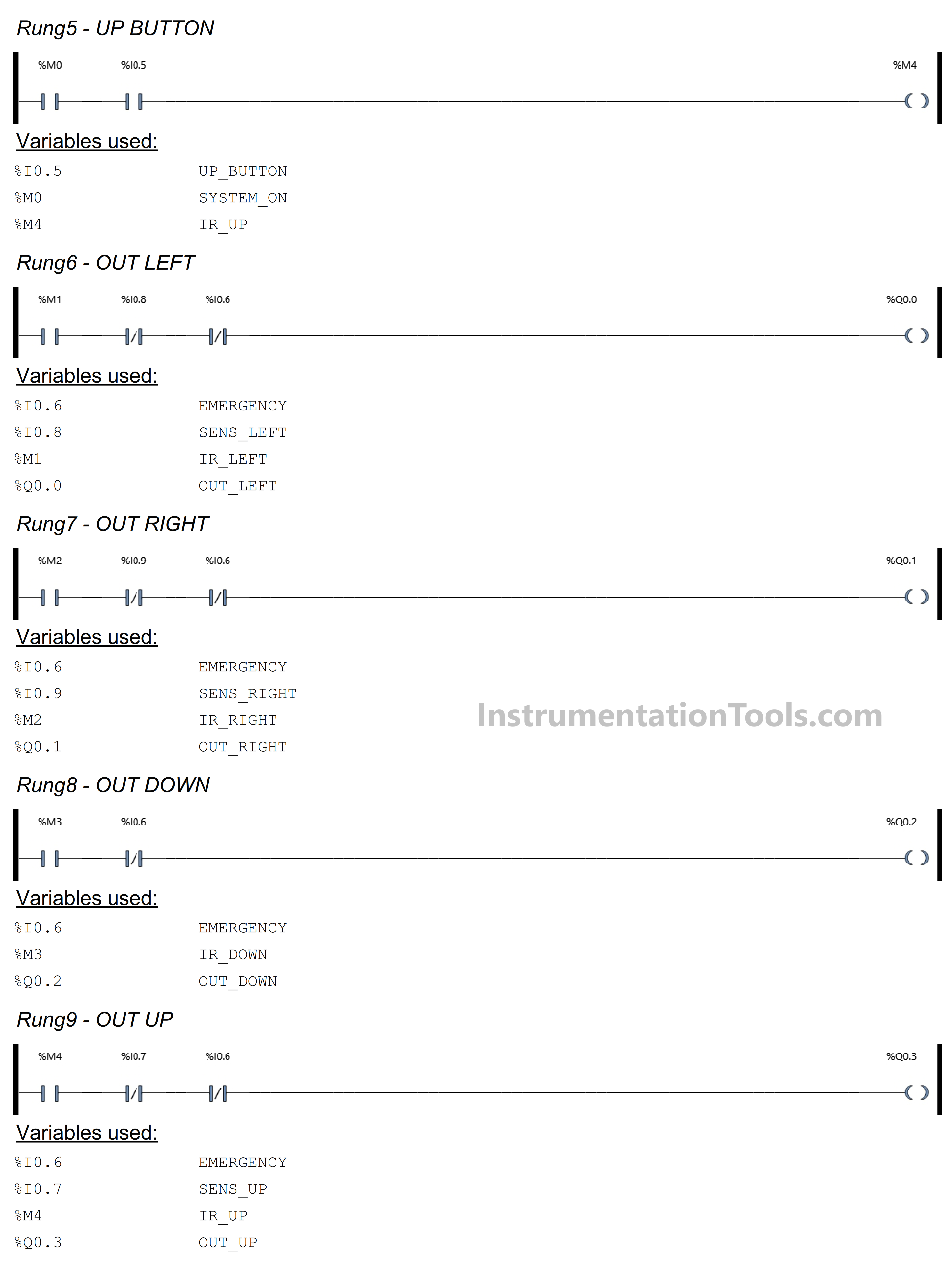
In this Rung, the memory bit IR_UP (M4) will be in the HIGH state if the NO contact of memory bit SYSTEM_ON (M0) in the HIGH state and the UP_BUTTON (I0.5) button is Pressed.
Example using Schneider PLC

RUNG 6 (OUT LEFT)

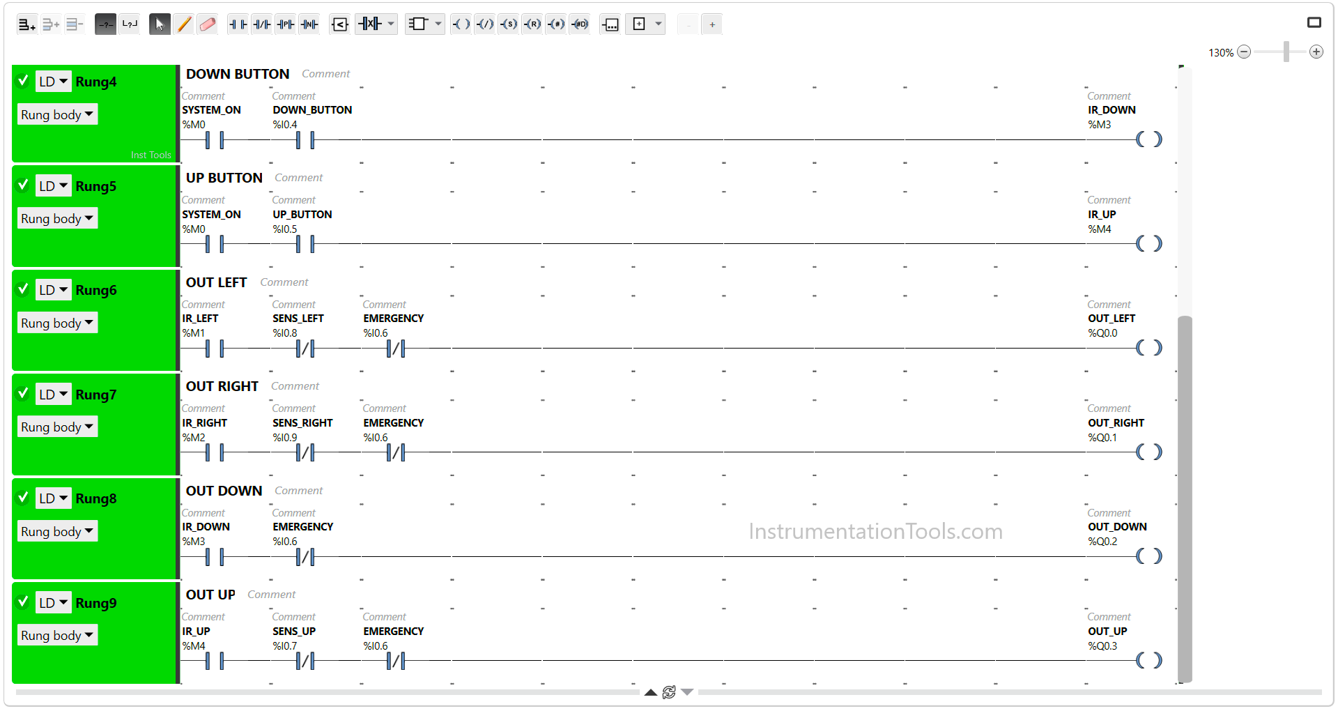
In this Rung, when the NO contact of memory bit IR_LEFT (M1) in the HIGH state, the Output OUT_LEFT (Q0.0) will be ON.

The OUT_LEFT (Q0.0) output will be OFF if the EMERGENCY (I0.6) button is Pressed or if the NC contact of Proximity Sensor SENS_LEFT (I0.8) in the HIGH state.

RUNG 7 (OUT RIGHT)

In this Rung, when the NO contact of memory bit IR_RIGHT (M2) in the HIGH state, the Output OUT_RIGHT (Q0.1) will be ON.

The OUT_RIGHT (Q0.1) output will be OFF if the EMERGENCY (I0.6) button is Pressed or if the NC contact of Proximity Sensor SENS_RIGHT (I0.9) in the HIGH state.

RUNG 8 (OUT DOWN)

In this Rung, when the memory bit IR_DOWN (M3) in the HIGH state, the Output OUT_DOWN (Q0.2) will be ON.

The OUT_DOWN (Q0.2) output will be OFF if the EMERGENCY (I0.6) button is Pressed.

RUNG 9 (OUT UP)

In this Rung, when the NO contact of memory bit IR_UP (M4) in the HIGH state, the Output OUT_UP (Q0.3) will be ON.

The OUT_UP (Q0.3) output will be OFF if the EMERGENCY (I0.6) button is Pressed or if the NC contact of Proximity Sensor SENS_UP (I0.7) in the HIGH state.

Read Next:

  • Conveyor Sorting with Color Detection
  • Difference Between PLC and CNC Machine
  • PLC Programming Clothes Washing System
  • PLC Example for Traffic Light FBD Program
  • PLC Program for Password Management
Don't Miss Our Updates
Be the first to get exclusive content straight to your email.
We promise not to spam you. You can unsubscribe at any time.
Invalid email address
You've successfully subscribed !

Continue Reading

How to Reduce Relay Noise in PLC Systems?
SCADA Communication and Protocols
System and Local Time in PLC
VFD Pros and Cons – Variable Frequency Drives
PLC Programming for Train Detection and Gate Operation
Multiple Pumps Control using PLC
Share This Article
Facebook Whatsapp Whatsapp LinkedIn Copy Link
Share
Leave a Comment

Leave a Reply Cancel reply

Your email address will not be published. Required fields are marked *

Stay Connected

128.3kFollowersLike
69.1kFollowersFollow
208kSubscribersSubscribe
38kFollowersFollow

Categories

Explore More

DCS versus PLC Architecture
Up Down Counter Instruction in PLC
PLC Program for Alarm Indication in Process Control
Value Assignments in SCL Language – Single, Multiple, Combined
How to Install GSD File in Step 7 PLC using Simatic Manager?
PLC Program for Temperature Control using Thermostat
#9 PLC Best Practices – Validate indirections
Conveyor Speed Logic using Structured Text in PLC

Keep Learning

PLC Program for 2 Push buttons to Control 1 Output

PLC Program for 2 Push buttons to Control 1 Output

How to Filter Digital and Analog Inputs in a PLC

#7 PLC Best Practices – Validate and Alert for Paired Inputs/Outputs

Shift Bit Register in PLC

Shift Bit Register in PLC

Classic Control Circuits

Motor Classic Control Circuits using Single Push button

One-Shot Rising and Falling Edge Instructions in Rockwell PLC

One-Shot Rising and Falling Edge Instructions in Rockwell PLC

Industrial Automation and Control Systems (IACS)

Industrial Automation and Control Systems (IACS)

Types of PLC

#14 PLC Best Practices – Restrict Third-party Data Interfaces

PLC Program for Food Processing

PLC Program for Food Processing Industry

Learn More

PLC Program for Filling Operation

PLC Program for Continuous Filling Operation

Explain What these Spool Valve Represent

Explain What these Spool Valve Symbols Represent?

RDOL starter

What are DOL and RDOL starters? Advantages, Disadvantages

DP Transmitters Level Measurement Principle

DP Transmitters Level Measurement Principle Video

What is a Flange Gasket ?

What is a Flange Gasket ?

Shutdown Manager

What are Pre-Shutdown, Shutdown, and Post-Shutdown?

Digital Electronics Objective Questions

Digital Electronics Objective Questions

Top 100 PLC Objective Questions and Answers

Top 100 PLC Objective Questions and Answers

Follow US
All rights reserved. Reproduction in whole or in part without written permission is prohibited.
Welcome Back!

Sign in to your account

Username or Email Address
Password

Lost your password?