Follow our step-by-step vibration probe commissioning checklist for the installation of vibration monitoring systems.
Vibration Probe Commissioning Checklist
Follow the below steps.
Pre-Installation Checks:
- Verify the vibration probe model and specifications.
- Check vibration probe calibration certificate.
- Inspect the vibration probe for any physical damage.
- Confirm that the mounting location is clean and prepared.
Mechanical Installation:
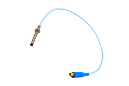
- Mount the vibration probe securely according to manufacturer guidelines.
- Ensure proper alignment with the shaft or surface to be monitored.
- Tighten all mounting hardware as per specifications.
- Verify that the vibration probe gap is within the required range.
Electrical Installation:
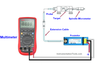
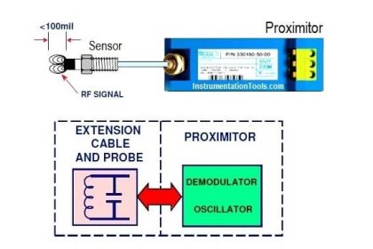
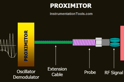
- Connect the vibration probe cable to the proximitor or driver or signal conditioner.
- Verify vibration proper cable routing to avoid electrical noise interference.
- Check for proper grounding and shielding of cables.
- Ensure that connectors are properly secured.
System Power-Up:
- Power up the system and ensure the vibration probe receives the correct supply voltage.
- Verify the output signal of the vibration probe with no machinery running (baseline reading).
- Check for any error messages or faults in the monitoring system.
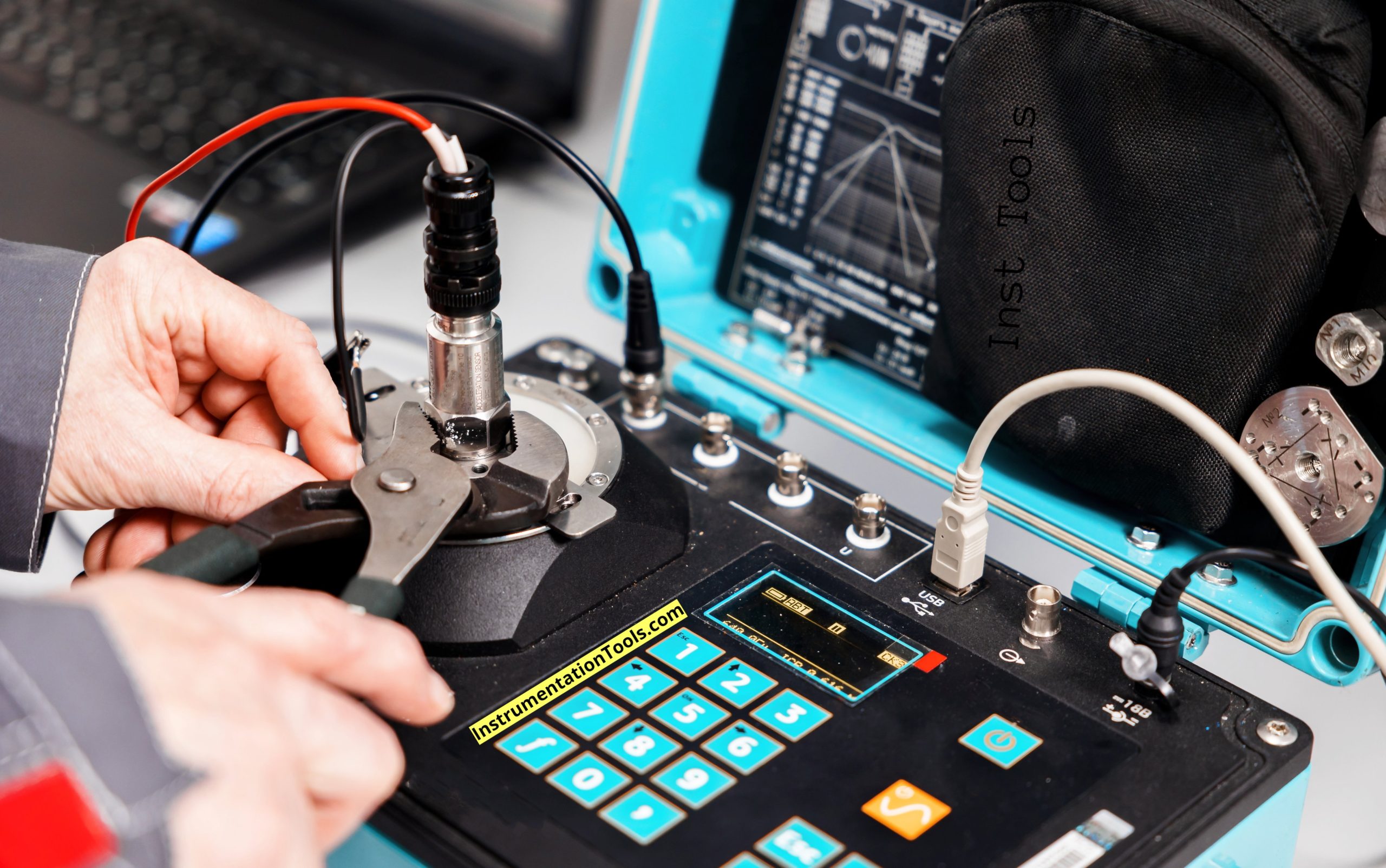
Gap Voltage Check:
- Measure the gap voltage and verify it’s within the specified range.
- Adjust the vibration probe position if necessary to achieve the correct gap voltage.
Signal Verification:
- Rotate the machine manually to check the vibration probe’s response.
- Verify that the vibration signal is being properly received and displayed on the monitoring system.
- Check the signal for noise or unexpected fluctuations.
Functional Testing:
- Run the machine at a slow speed and verify the vibration probe’s output. (if available)
- Gradually increase speed to normal operating conditions and monitor the signal.
- Compare the measured vibration levels with expected values or baselines.
System Integration:
- Verify the vibration probe’s integration with the overall monitoring system.
- Check alarm and trip settings for accuracy.
- Test the response of the system to simulated vibration levels (if applicable).
Documentation:
- Record all gap voltage readings and signal checks.
- Document any adjustments made during commissioning.
- Complete the commissioning report with all relevant data.
Summary:
- Confirm all system parameters are within acceptable limits.
- Verify that the vibration probe is functioning correctly.
- Ensure all safety interlocks are active and correctly configured.
- Obtain sign-off from all relevant stakeholders.
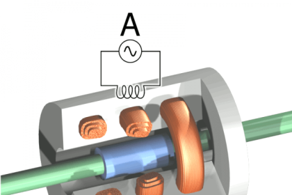
Vibration Monitoring Systems
Make sure to check the main points which are mentioned below.
Ensure the instrument aligns with the detailed specifications provided in the documentation.
Verify that all wiring follows the electrical schematics precisely.
Make sure the power supply is securely connected and delivering the appropriate voltage.
Confirm that the vibration probe is accurately calibrated and that the trip points are set according to operational requirements.
Adjust the probe gap to the correct distance to ensure precise measurement.
Check the functionality of the shutdown bypass to ensure it operates correctly during maintenance activities.
Ensure low-voltage Proximitor cables are routed separately from power cables to prevent interference.
Test each alarm and indicator point to confirm it triggers the correct response in the system.
Inspect all Proximitors and BNC connectors for any loose or insecure wiring connections.
These steps are important for the proper commissioning and good operation of vibration monitoring systems.
Read Next:
- Interview Questions on Vibration Measurement
- AND Logic in Bently Nevada Vibration System
- Bently Nevada Vibration System Verification
- Vibration Probe Field Setting Procedure
- 3500 Machinery Protection Systems Modules