Basic PLC exercise on heater and cooler based on the low-level and high-level temperature sensors for students.
Note: Before proceeding further with this PLC programming example please consider that this program is for education to learn ladder logic.
Heater and Cooler PLC Exercise
Problem Statement:
Design a PLC ladder logic for the following application.
We are using one toggle switch and two Sensors to control the Heater and Cooler.
If the Low-Temperature Sensor gets activated (temperature is below 25 degrees), a heater should run for 45 seconds.
If the High-Temperature Sensor gets activated ( Temperature is above 30 degrees), a cooler should run for 45 seconds.
Ladder Logic Videos
The best ladder logic training videos are available on the Instrumentation Tools YouTube channel. Try them for free of cost.
This video explains the mentioned PLC problem statement with detailed steps.
Inputs and Outputs
Digital Inputs:
Start Button: I0.0
Low Temperature Sensor: I0.1
High Temperature Sensor: I0.2
Digital Outputs:
Heater: Q0.0
Cooler: Q0.1
PLC Program
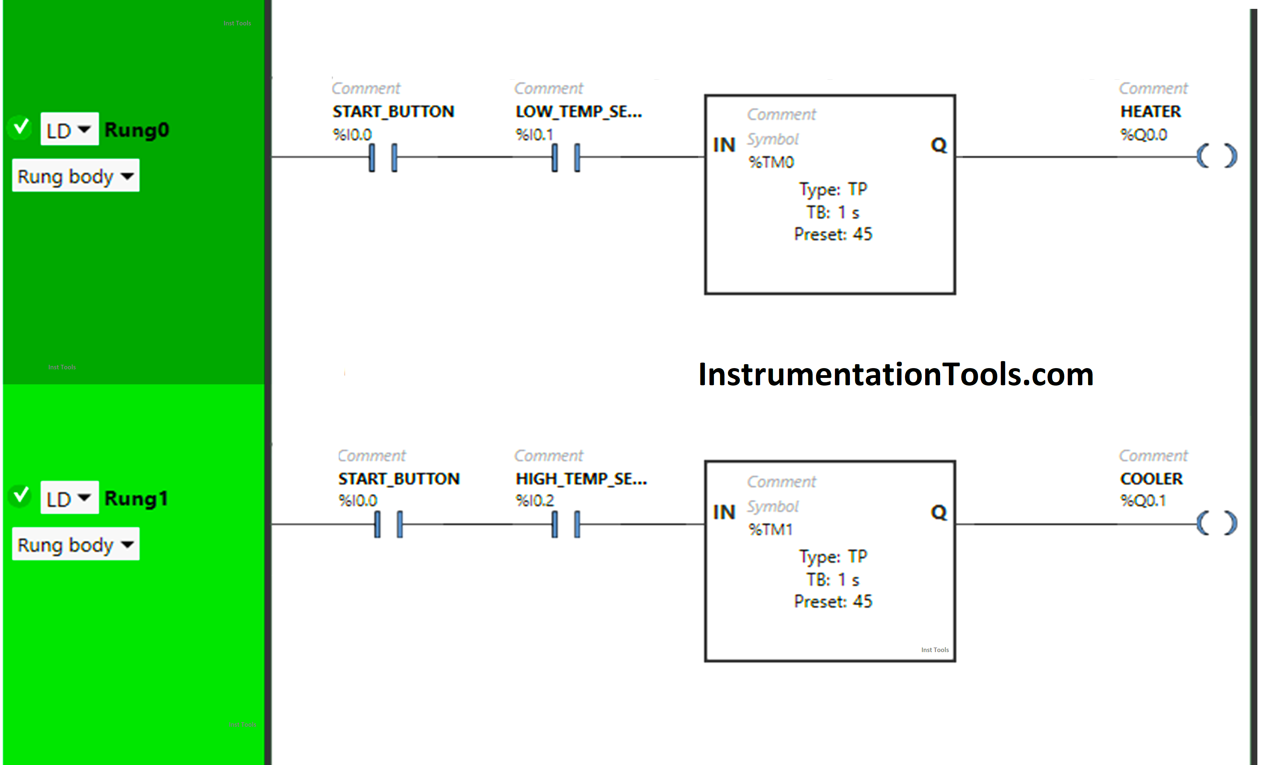
Program Description
We have used Normally Open Contact for the Start Button(I0.0), Low-Temperature Sensor (I0.1), and High-Temperature Sensor (Q0.2).
In Rung 0:
- Normally Open Contact is used for Start Button (I0.0) and Low Temperature Sensor (I0.1) to turn ON the output Heater (Q0.0).
- Timer-type TP is used to Turn ON the output Heater (Q0.0) for a limited time.
In Rung 1:
- Normally Open Contact is used for the Start Button (I0.0) and High Temperature Sensor (I0.2) to turn ON the output Cooler (Q0.1).
- Timer-type TP is used to Turn ON the output Cooler (Q0.1) for a limited time.
Program Simulation Results
We simulated our PLC program and analyze the results.
Rung 0:
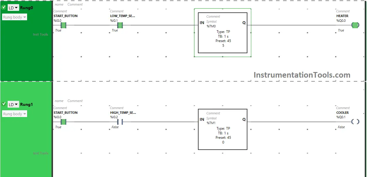
When the Start Button (I0.0) is turned ON and the Low-Temperature sensor (I0.1) gets activated, the signal will flow through the Start Button (I0.0) and Low-Temperature Sensor (I0.1) as Normally Open Contact is used for the Start Button (I0.0) and Low-Temperature Sensor (I0.1).
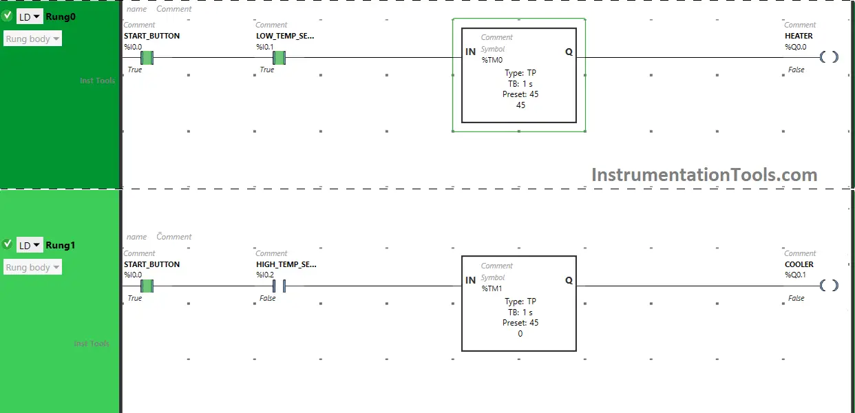
The output Heater (Q0.0) turns ON for 45 seconds because Timer Function Block type TP is used to turn ON the output Heater (Q0.0) for a limited time and the time is set to 45 seconds. After 45 seconds, the output Heater (Q0.0) will turn OFF.
Rung 1:
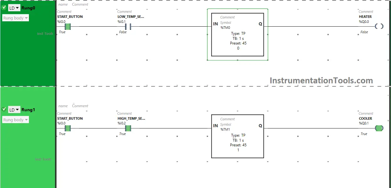
When the Start Button (I0.0) is turned ON and the High-Temperature sensor (I0.2) gets activated, the signal will flow through the Start Button (I0.0) and High-Temperature Sensor (I0.2) as Normally Open Contact is used for the Start Button (I0.0) and High-Temperature Sensor (I0.2).
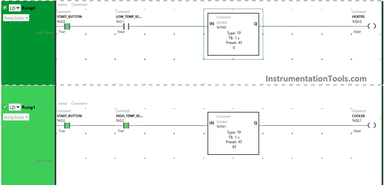
The output Cooler (Q0.1) turns ON for 45 seconds because Timer Function Block type TP is used to turn ON the output Cooler (Q0.1) for a limited time and the time is set to 45 seconds. After 45 seconds, the output Cooler (Q0.1) will turn OFF.
If you liked this article, please subscribe to our YouTube Channel for PLC and SCADA video tutorials.
You can also follow us on Facebook and Twitter to receive daily updates.
Read Next:
- PLC Program with 5-Second Floor Stops
- PLC Programming for Barrier Control
- Traffic Lights PLC Logic using Timers
- PLC Logic for Water Pumping System
- PLC Conveyor Forward and Reverse


It’s very useful specially for the beginner.
Interesting