In previous articles, we introduced the concept of distributed IO modules, and how to configure an IO module with a PLC. In this article, we will show how to do Distributed IO Sharing Between PLC Systems.
Contents:
- Problem description.
- Sharing the IO device with two PLCs.
- Assigning different internal modules to PLCs.
Problem description
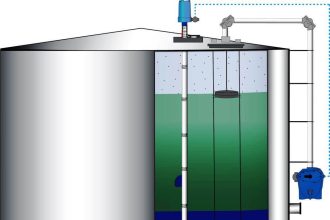
In the previous article, we showed how we can connect and configure a distributed IO module with a PLC and control the IO points of the Distributed module through that PLC. In this article, we discuss the case when we need to use the same distributed IO module with two different PLCs. See picture 1.
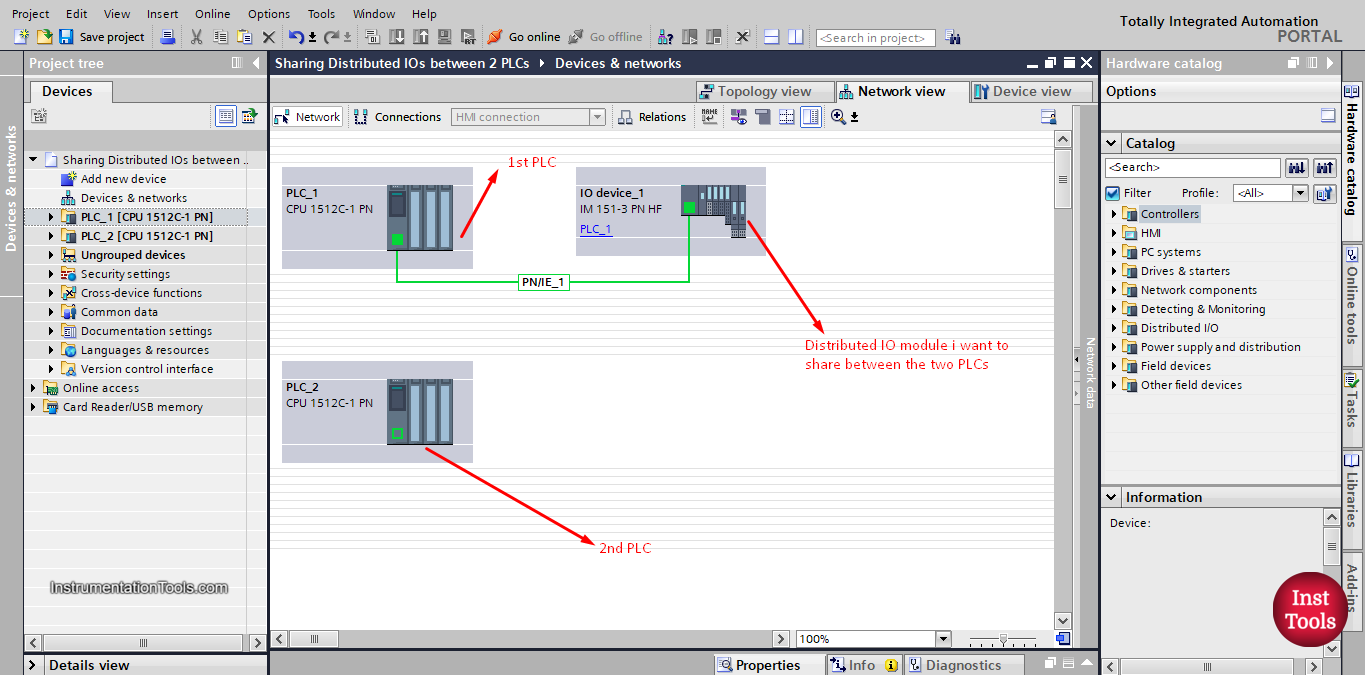
Picture 1. Two different PLC projects.
Distributed IO Sharing Between PLC Systems
Imagine that we need to share the inputs and outputs points of the distributed module between the two PLCs. Sharing a distributed IO module between two PLCs is possible but not all modules can do that, but most modern ones can.
Another way to share the information would be to get all the information from the distributed IO to one PLC and establish communication between the two PLCs and then exchange the needed data. This will be shown in another article.
In the distributed IO device (IO device_1) we have configured many IO modules such as 4DIx24VDC module, 8DOx24VDC module, 2DIx24VDC module, and some more modules. See picture 2.
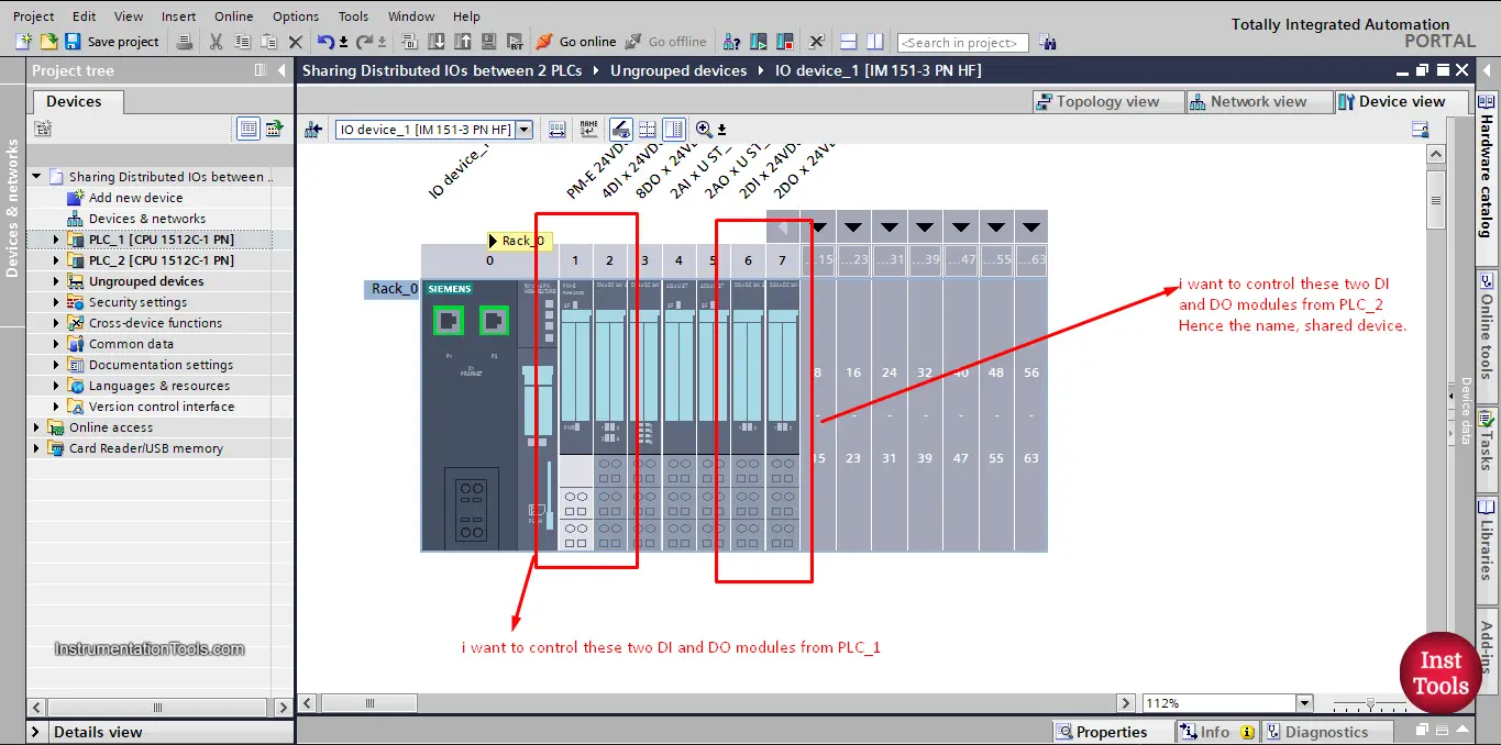
picture 2. Different IO modules in our IO device.
Sharing the IO device with two PLCs
In this article, we will assume as you see from the picture that we want to control the 4DIx24VDC module and 8DOx24VDC module through PLC_1 and I want to control the 2DIx24VDC module and, 2DOx24VDC module from PLC_2.
So I want to share the different modules between the two PLCs, hence the name-sharing devices.
As you can see in picture 1, the distributed IO device (IO device_1) is already an extension of PLC_1as we set that up in the previous article, but we also need to make it an extension of PLC_2 so it can be shared between the two PLCs. See picture 3.
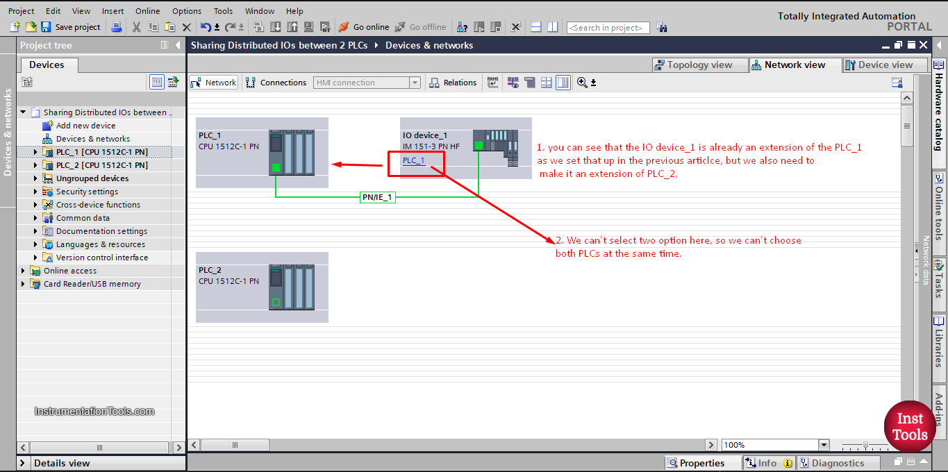
picture 3. IO device is an extension of PLC_1
Usually, when doing that we would have each PLC on a different TIA Portal project, but as we don’t have real hardware devices, we will just use one TIA Portal software project to show how to share the distributed IO module between the two PLCs.
We have one project with two PLCs. And we need to assign the IO device_1to the PLC_1 and PLC_2
To do that, copy the module in the Network view and paste it to have two modules in your project. See picture 4.
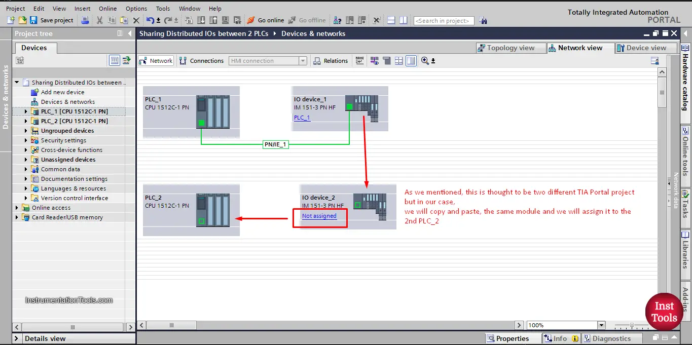
picture 4. Copy and paste the IO device.
Now, we need to assign this IO device to the PLC_2, as we did with PLC_1 in the last article. See picture 5.
picture 5. Assign the module to PLC_2
NOW, if you try to download your project to both PLCs, the PLC_1 will be able to find the IO module. However, PLC_2 will not be able to find the IO module because there is no actual hardware module that is named IO device_2, we have only one hardware IO device and from last article it was configured with the name IO device_1 that is why the PLC_2 will not find the IO device. See picture 6.
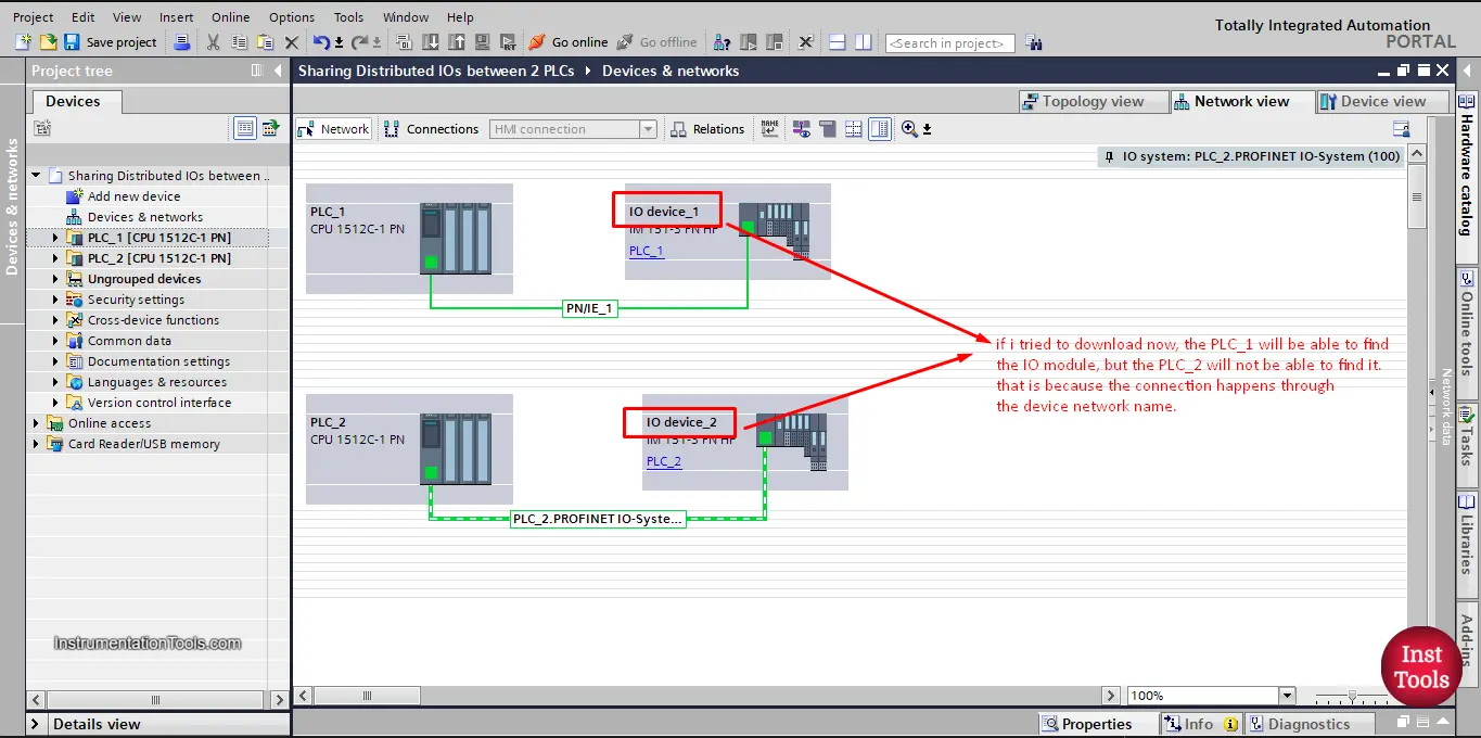
picture 6. Connection is made through Device Network Name.
So, we need to give the same device network name to both IO modules, see picture 7.
picture 7. Network device name
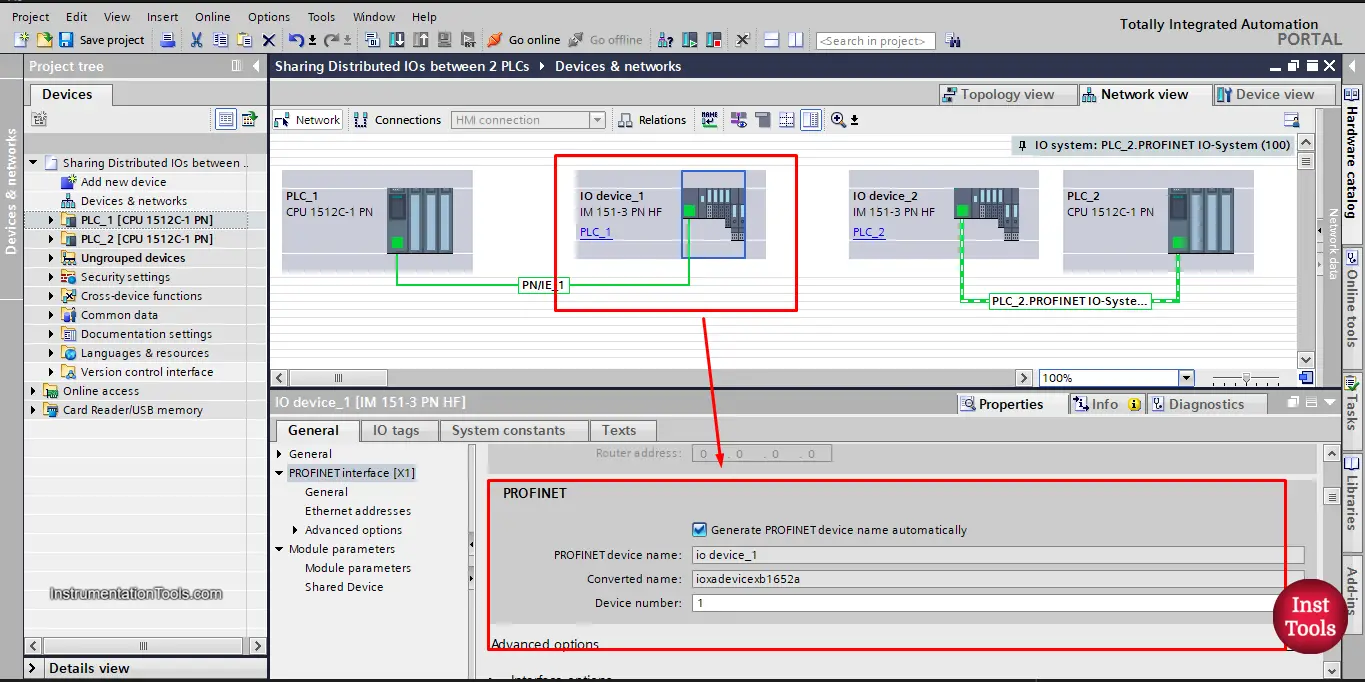
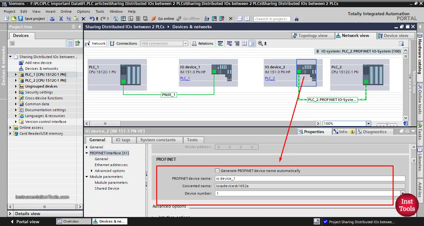
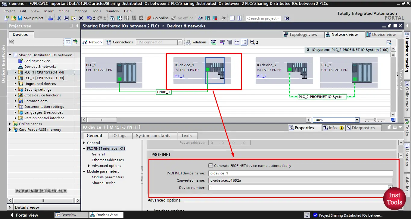
As you can see, the Network Device Name for the IO module is IO device_1, see picture 8 for the other IO module.
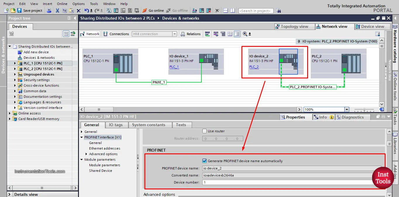
picture 8. Network Device Name for the 2nd IO module.
Here, the network name is IO device_2. We need to give both IO modules the same name so both PLCs can find it and connect to it.
Unclick the automatic name generation option so we can change the name and make both of them IO device_1, also make sure that all information inside the red area is the same in both modules. See picture 9.
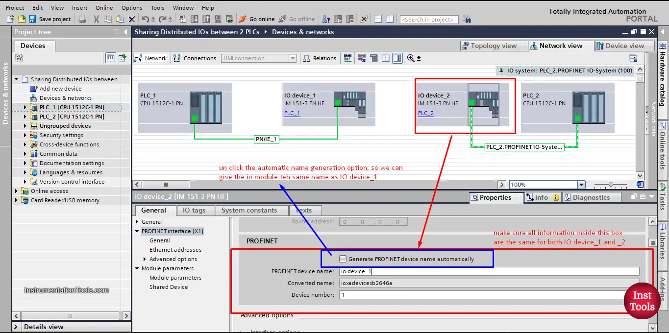
picture 9. Unclick the automatic generation option.
Check pictures 10a and 10b after we changed the information to be the same for both modules.
Picture 10a. 2nd IO module.
Picture 10b. 1st IO module
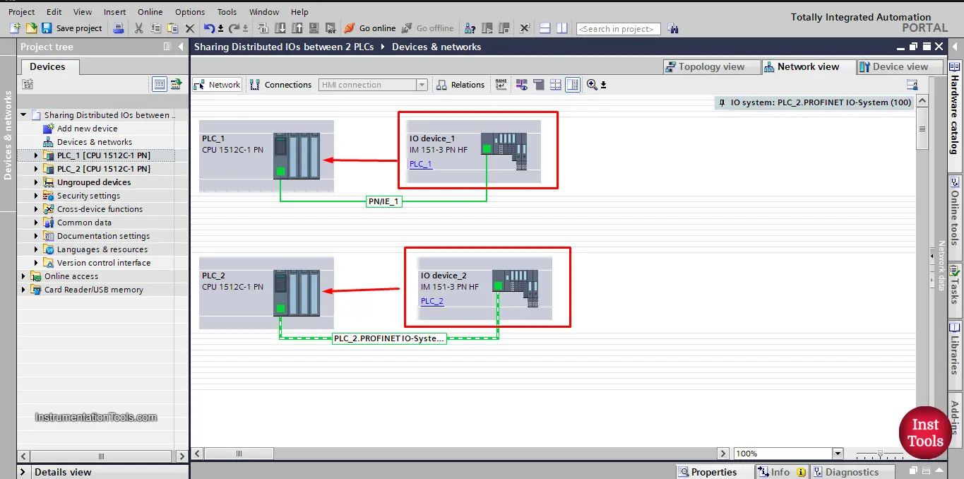
Now that the two IO modules are identical, both PLCs can find and communicate with the IO module. See picture 11.
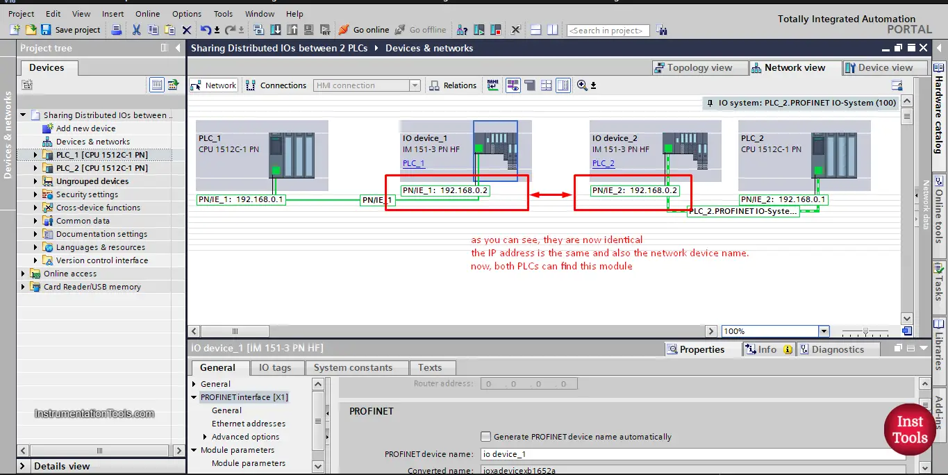
picture 11. Both PLCs can find the IO module.
Up until this point, we were assuming that both PLCs are within the same TIA Portal project.
But, in case we are sharing the IO module with a controller in another TIA Portal project, we will do the same as before but we will add an extra step.
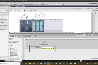
In this step, we will go to the properties of the IO module and change the shared device IO cycle option as you see in picture 12.
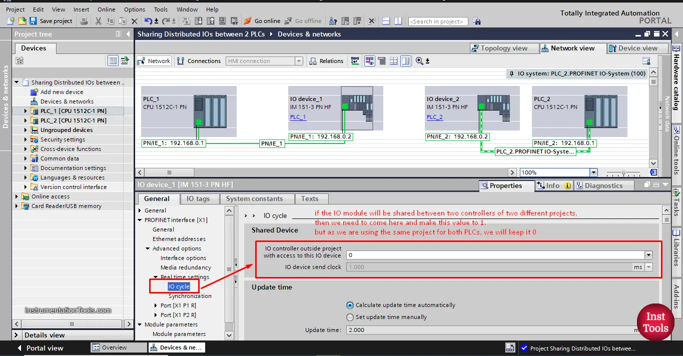
picture 12. IO controller outside the project
As you can see from the picture, if the two PLCs are of different TIA Portal projects, we will change the value inside the red box to 1.
As we have both PLCs in the same project we will keep it zero.
Now that both PLCs can see and communicate with the IO device, we need to tell the IO module, which internal modules should communicate with which PLC.
As we mentioned in picture 2, we need a 4DIx24VDC module and 8DOx24VDC module to communicate withPLC_1 and I want to control the 2DIx24VDC module and 2DOx24VDC module from PLC_2.
We can do that by following the following steps.
Assigning different internal modules to PLCs
Start by going to the properties of the IO device_1, you will find that all internal modules of the IO device belong to PLC_1. See picture 13.
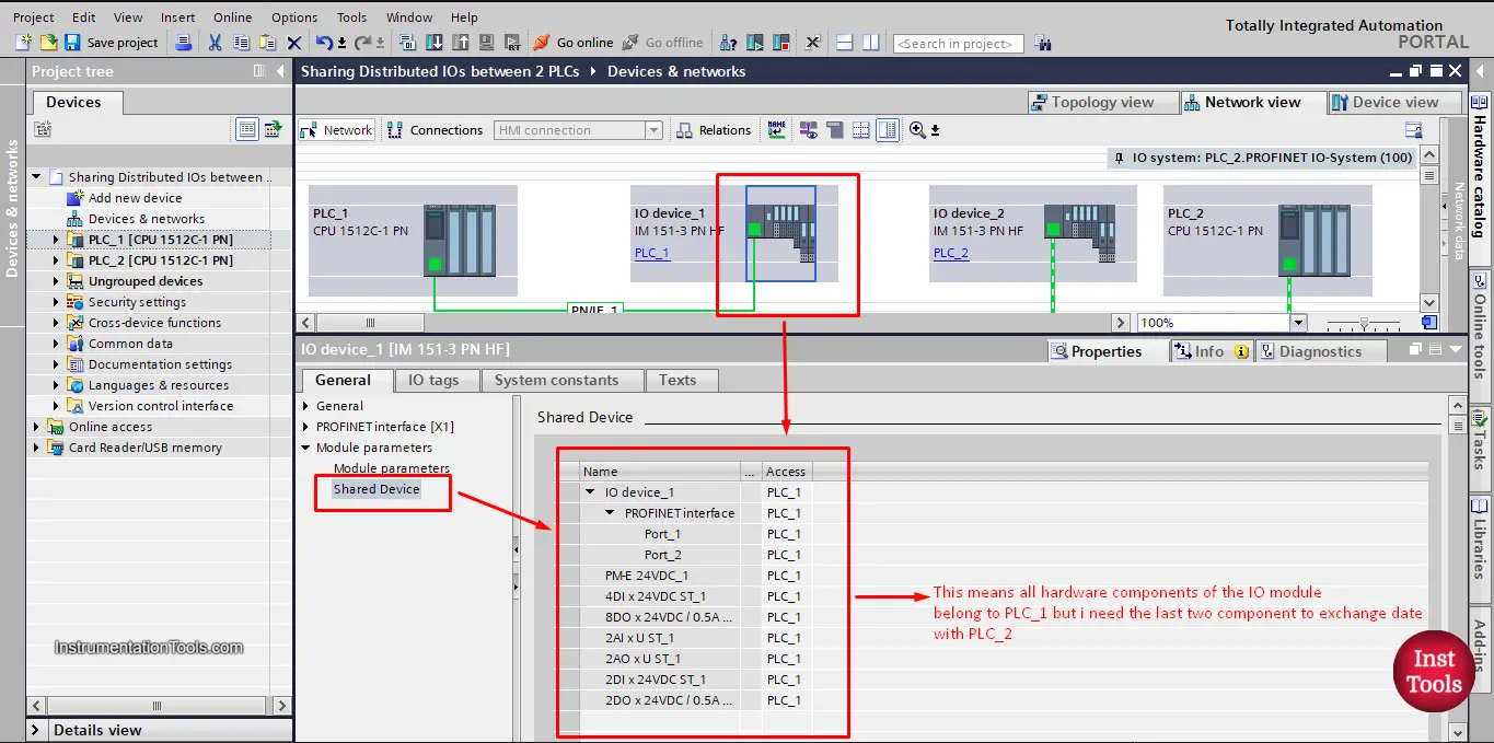
picture 13. Shared device of the IO module.
As you can see from the picture, accessing all internal modules of the IO device is assigned to PLC_1, but as we mentioned before we need the last two internal modules 2DIx24VDC module and 2DOx24VDC module to be accessed by PLC_2.
To do so, just right-click the module you want and unselect the PLC_1 option, and make it blank to indicate that this module will be controlled through a different controller. See picture 14.
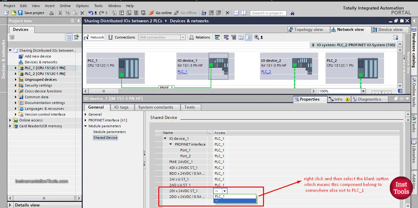
picture 14. Unselect internal modules.
If you check the device overview of the IO device_1 after you unselect the PLC_1 option, you will see that those internal modules have no addressing assigned with the PLC_1 indicating they belong somewhere else. See picture 15.
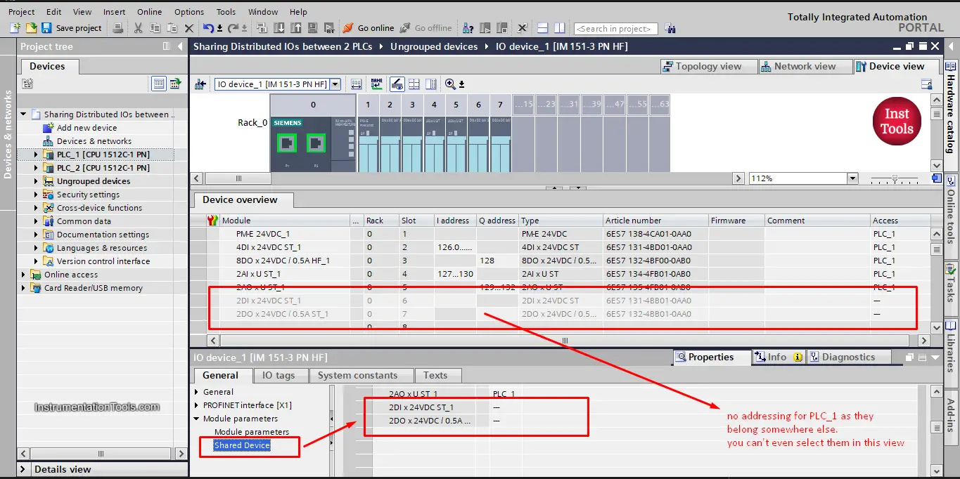
picture 15. No addressing for modules not assigned to PLC_1
NOW, I need to assign those two modules to the IO device_2 for PLC_2.
By doing the same steps as before, go to the shared device properties of the IO device_2, and assign only the two needed modules with PLC_2. See picture 16.
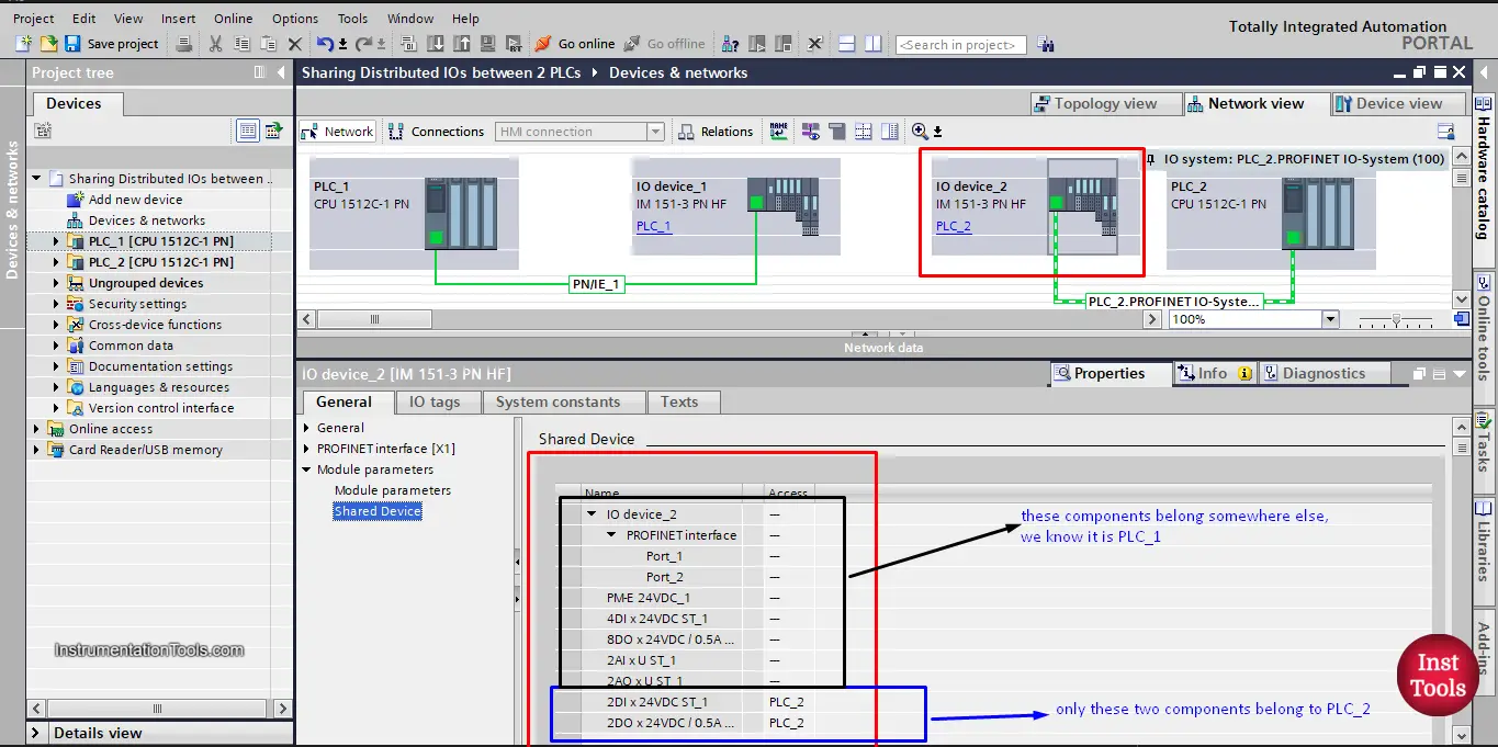
picture 16. Assign needed modules to PLC_2
Now that the 2DIx24VDC module and 2DOx24VDC module are assigned to PLC_2, if you check the device overview you will find their addressing with PLC_2 as we want. See picture 17.
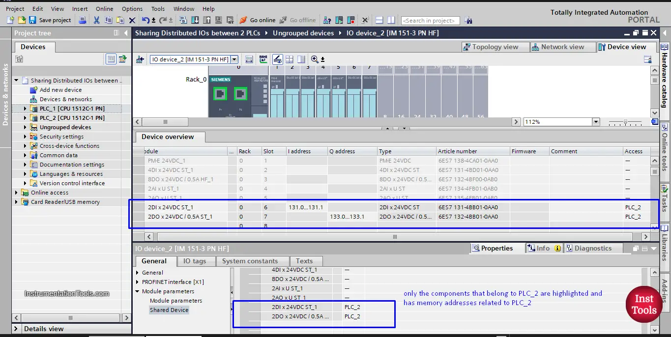
picture 17. Addressing belong to PLC_2
That is how we can share one IO module between two PLCs, whether they are in the same TIA Portal project or in two different projects.
If you liked this article, then please subscribe to our YouTube Channel for Instrumentation, Electrical, PLC, and SCADA video tutorials.
You can also follow us on Facebook and Twitter to receive daily updates.
Read Next:
- PLC Sizes and Applications
- One-Shot Rising and Falling Edge
- Software in Rockwell Automation
- S7-1200 Hardware Configuration
- Factory IO and Siemens Tia Portal