Pneumatics is the process of controlling and actuating the output elements with the help of compressed air. In this, we used a pneumatic counter for counting the strokes of the cylinder and automatically shut off the process once we got the defined count.
This application is used in conveyor assembly, and punching processes where the process is required to be done for a particular count and then it needs to be stopped. Further actuation will be started after the confirmation of the input from the user.
Components of Pneumatic Counter
The main components of a pneumatic counter as listed below.
- Compressor
- 3/2 Push Button
- Limit Switches
- 3/2 Pneumatic actuated Directional Control Valve
- 5/2 Pneumatic actuated Directional Control Valve
- Double acting Cylinder
- Pneumatic Counter
Compressor
A compressor is a machine that compresses air or another type of gas from low inlet pressure to a higher desired pressure level. This is achieved by reducing the volume of the gas. Air compressors are generally positive displacement units in the type of reciprocating piston type or rotary screw or rotary vane type.
A compressor acts as an input source for the pneumatic system which supplies the compressed air to do all the control and actuating operations.
3/2 Push Button
3/2 push button the name indicates it has 3 ports and 2 switching positions. 3 ports are the inlet, outlet, and exhaust. In the inlet port, the compressed air supply is given whereas from the output port, the compressed air is given to the actuator or control valve.
The exhaust valve is used to return the air supply to the environment by using a silencer. The movement of two positions sets the direction for the air movement. This push button’s reverse actuation is done by the spring.
Limit Switches
Limit switches are the devices used to determine the end position of the cylinder. It is similar to a 3/2 push button (Direction Control valve). The only difference is, that it is a mechanically actuated one and the push button is a manually operated one.
The movement of the cylinder defines the actuation of the limit switches and this also has spring returned action.
3/2 Pneumatic Actuated Direction Control Valve
This Direction Control Valve also has 3 ports and 2 switching positions as per the name indication. The actuation method is controlled by compressed air only.
That means the two switching positions in the valve are done by the compressed air, not by any mechanical or manual operation. Both sides’ movement is done by the air only not any spring returned method is used in this method.
5/2 Pneumatic actuated Direction Control Valve:
As the name indicates it has 5 ports and 2 switching positions. Because of the pneumatic actuation both of the switching positions were done by the compressed air only. No spring mechanism is used for the return movement.
5 ports include 1 input, 2 outputs, and 2 exhausts where at input the compressed air is given, 2 outputs are connected to the actuators or control valves, and at last, through the exhaust, the returned air is exhausted in the environment.
Double Acting Cylinder
A double-acting cylinder is the actuator in the pneumatic systems. It is the most commonly used actuator in the pneumatic system.
A double in the cylinder indicates it has two ports, one for forward movement and one for reverse movement. Depending on the supply given to the ports it will move forward or backward.
Pneumatic Counter
A pneumatic Counter is used to count the counting done on the system, it may be either cylinder stroke movement, or limit switch actuation like that. It has four ports including input, output, signal, and reset.
In input ports the compressed air supply is given, the output supply gives the signal to the control valves, the signal port is used for counting, reset port is used to reset the counted values in the counter.
The function of the counter is used to count the strokes and after getting the preset count it gives the output. It will be reset by giving the signal to the reset port.
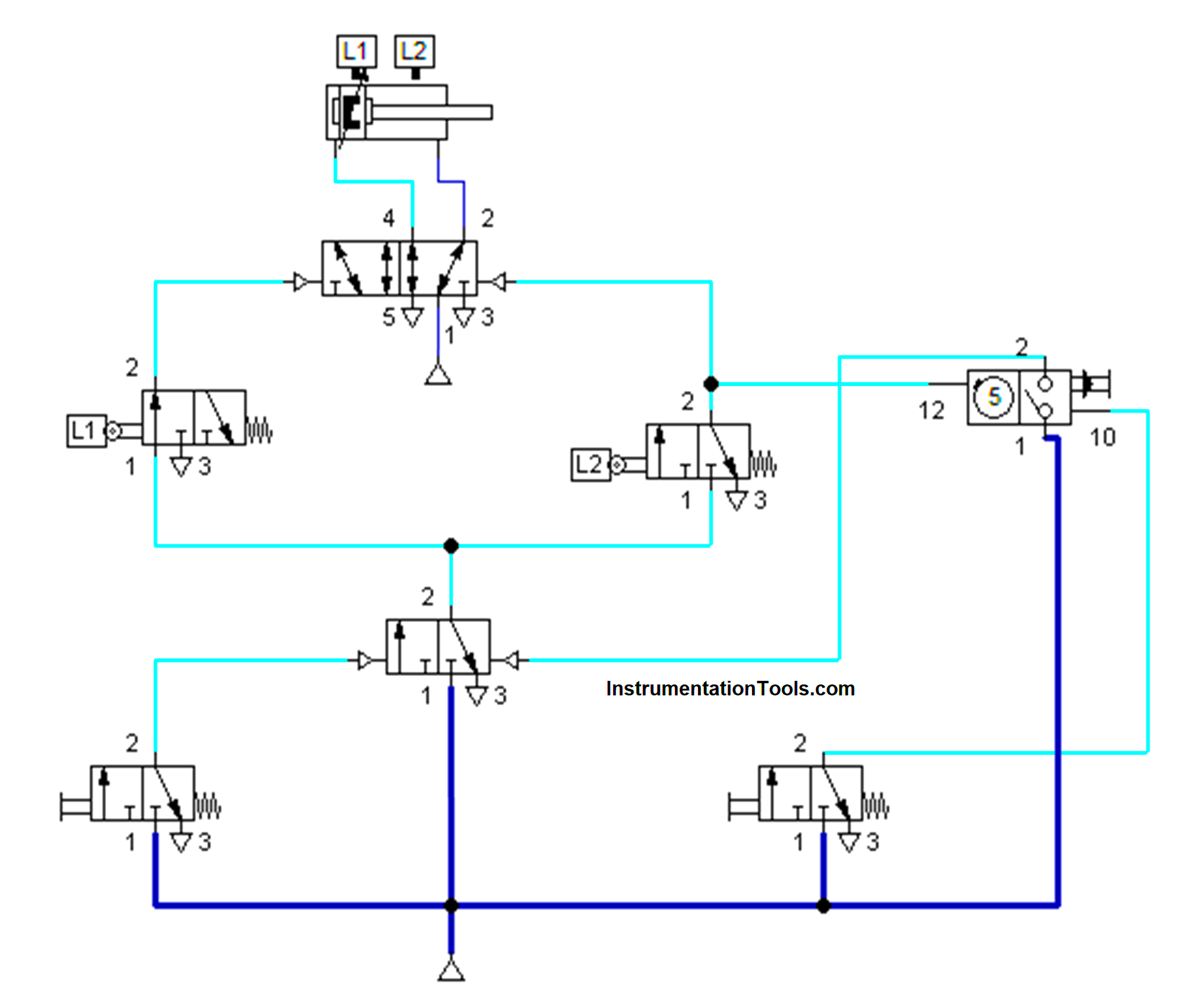
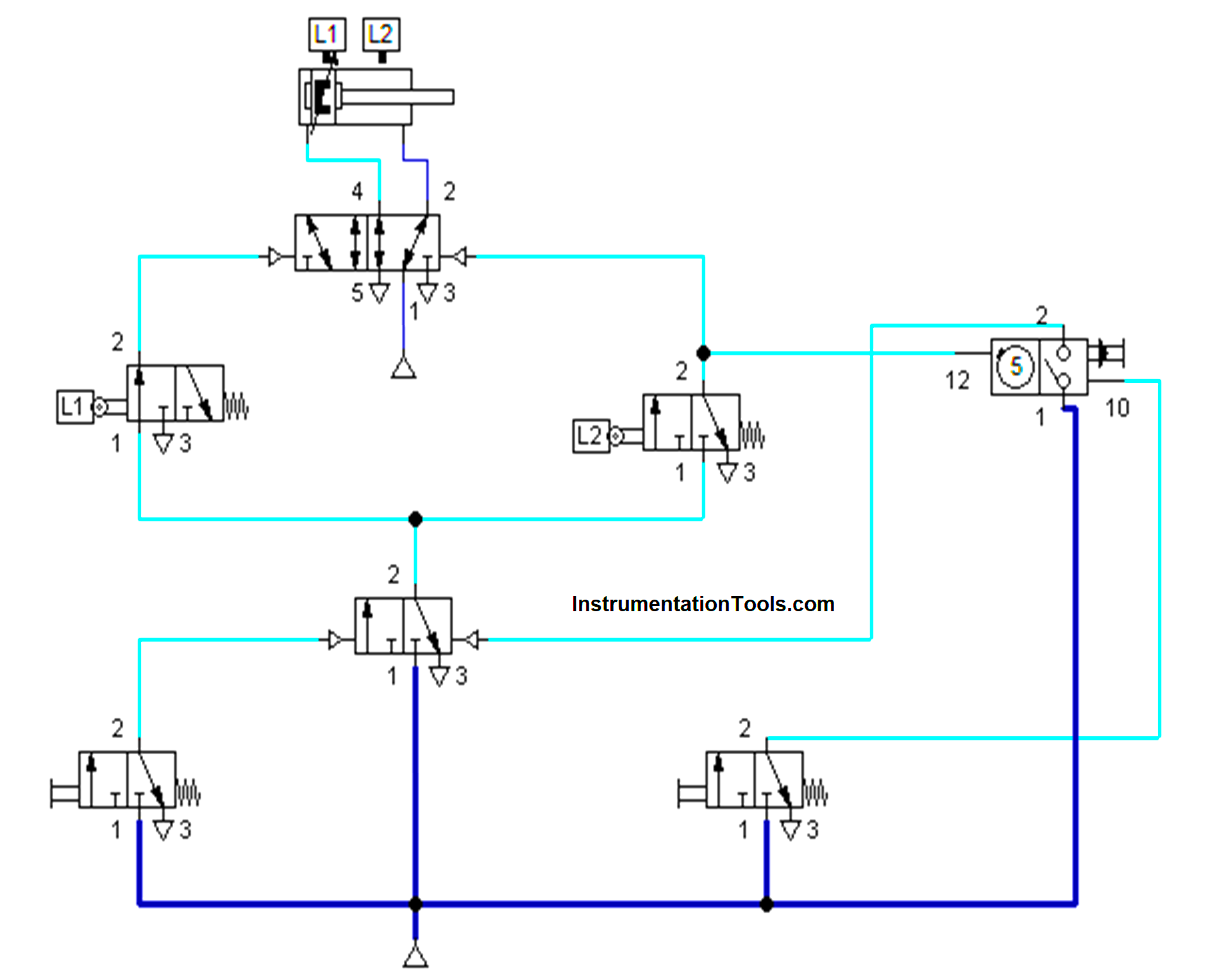
Pneumatic Counter Circuit Diagram
The pneumatic counter circuit diagram is shown below.
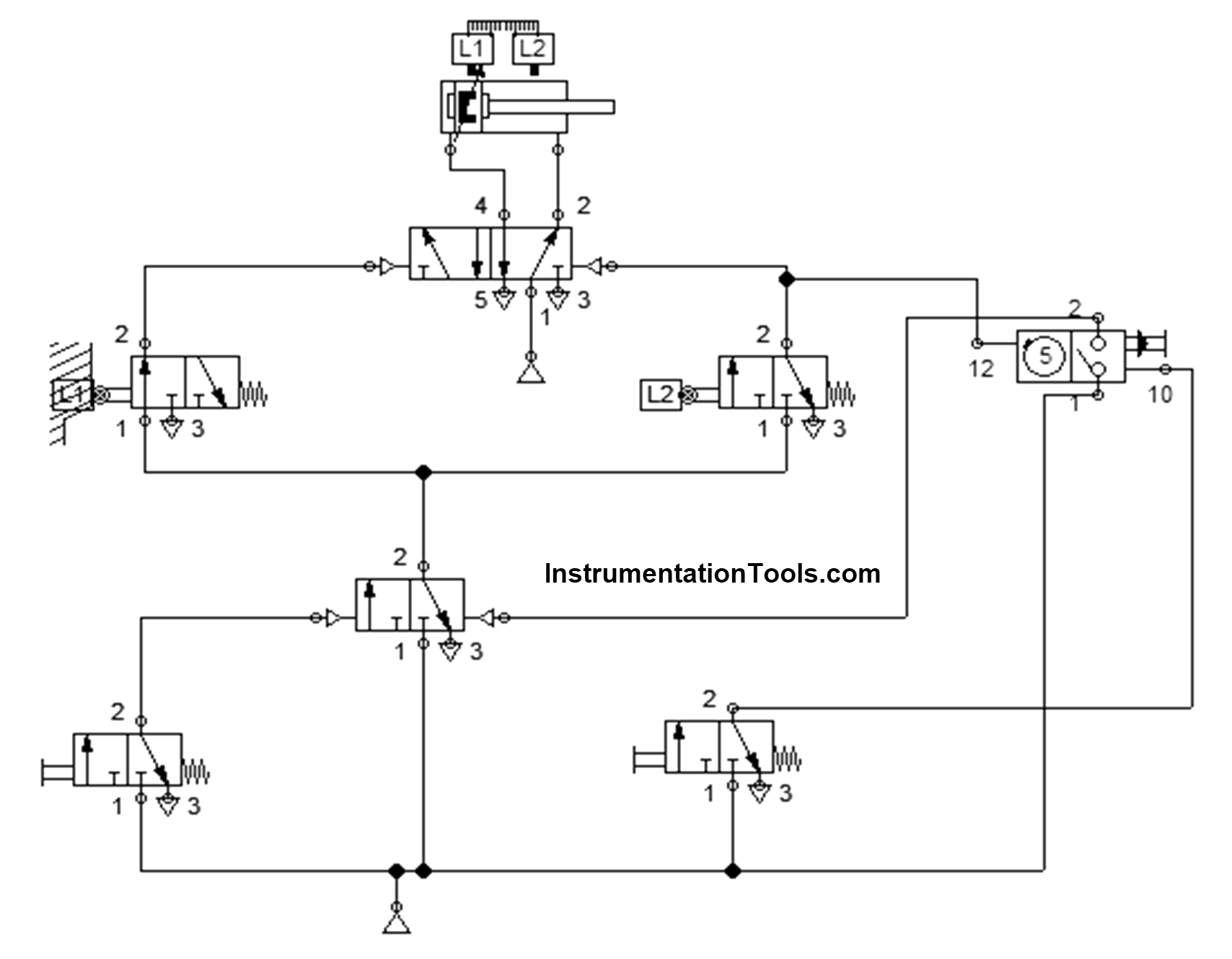
Pneumatic Counter Working Principle
The air supply is given to the system and the cylinder was in its home position with the contact of Limit switch 1.
When the Push button is pushed, the supply goes to the 3/2 Pneumatic actuated directional control valve.
We connected the output of the 3/2 pneumatic actuated valve to the limit switches for switching the positions of the 5/2 pneumatic actuated valve.
The switching positions of 5/2 directional control valves make the cylinder move forward.
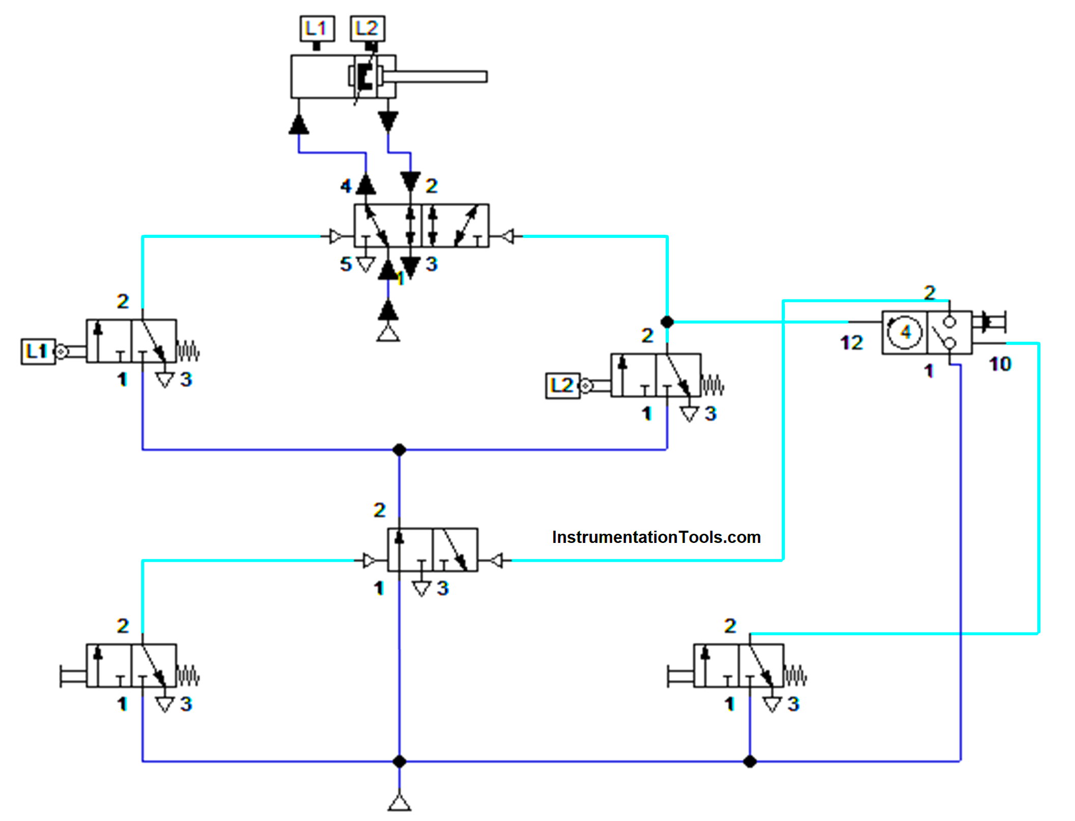
The cylinder moves forward and touches its end position which was identified by the Limit switch 2. This made the cylinder move backward and that time count was counted with the help of a pneumatic counter.
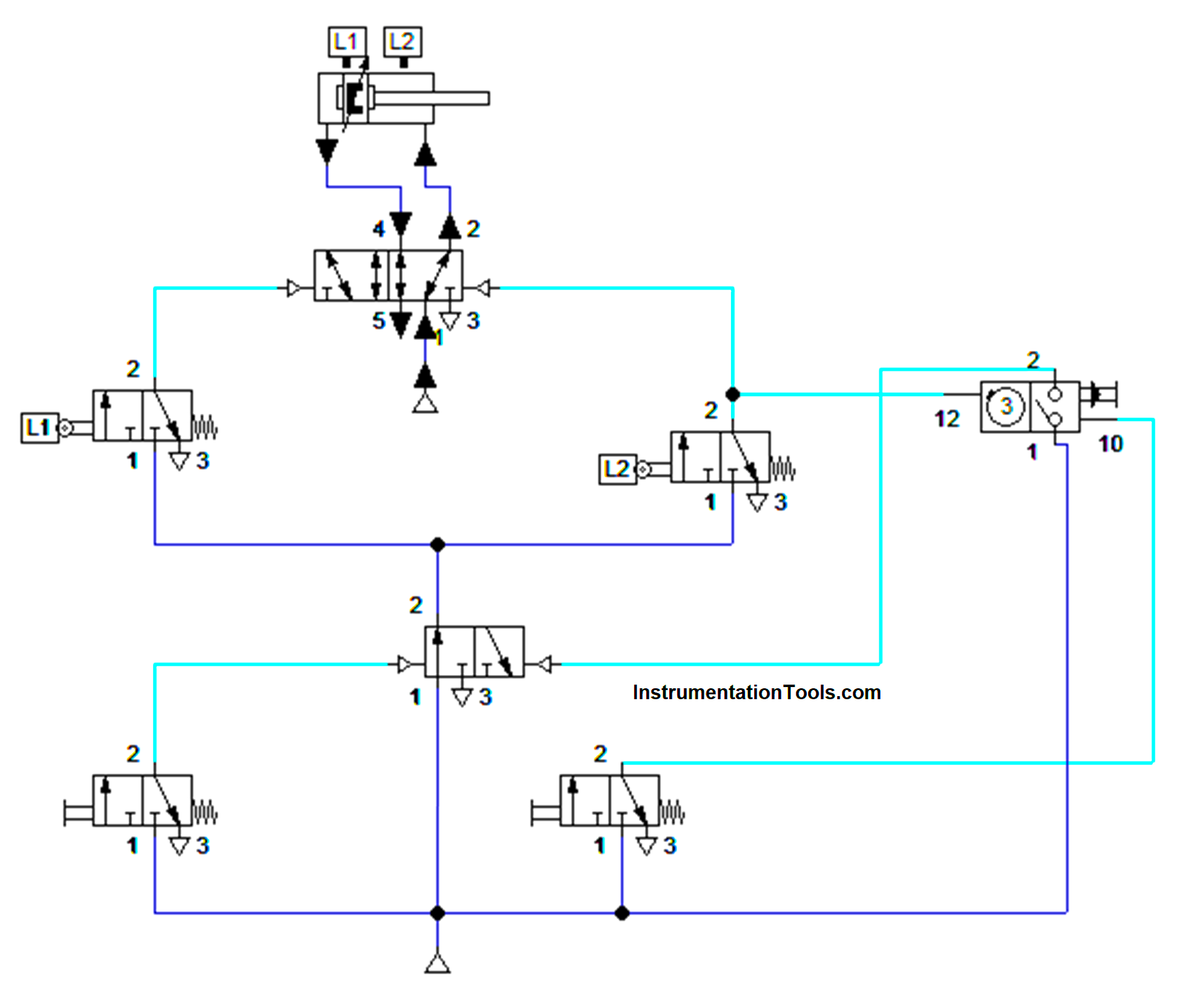
Again this cylinder comes to the home position and touches the limit switch 1 which makes the cylinder move forward.
Then the cylinder moves forward and the process continues. At the same time cylinder stroke was counted by the pneumatic counter.
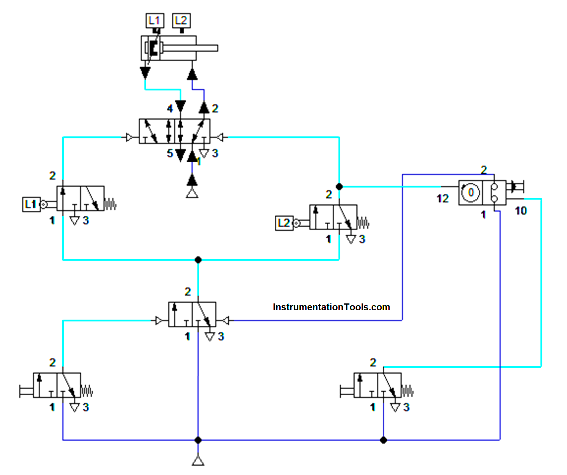
After obtaining the defined value in the counter, the process gets stopped. The cylinder will be in the home position only. Even if we restart the process also it won’t work. It will work only after we reset the pneumatic counter.
The pneumatic counter was reset by using a separate push button. So, by this method, the cylinder stroke was counted and it was deployed as per the application.
Conclusion
This method can be used in the applications of sorting, conveyor assembly, gang drilling, etc. We can give the counter input as per the needs and as per the component specification. This will save more time and manual counting errors.