In this article, we will study what condensate automation is? And what is the purpose of it?
The condensate automation systems are mainly employed in the sugar industry, distillery, paper industry, chemical industry, and so on.
The purpose of the condensate automation system is to cool down or reduce the temperature of the exhaust steam and the vapor outlet.
But in this article, we will discuss the condenser in the vacuum pan in the sugar industry.
Principle of Condenser Automation in Vacuum Pan
- As the massecuite level in the pan rises, the rate of evaporation is reduced and therefore water required to create the vacuum is less.
- When the vapor is mixed with injected water in the pan and the vacuum is created at the outlet tailpipe.
- The temperature difference between vapor and vapor-condensate also affects vacuum generation.
- The injection of water reduces the temperature as per Ambient.
Purpose of Condenser Automation
To control the water with respect to vacuum vapor and NCG load. Condenser automation reduces the water and steam requirement. And to facilitate the required vacuum generation using optimum water and power.
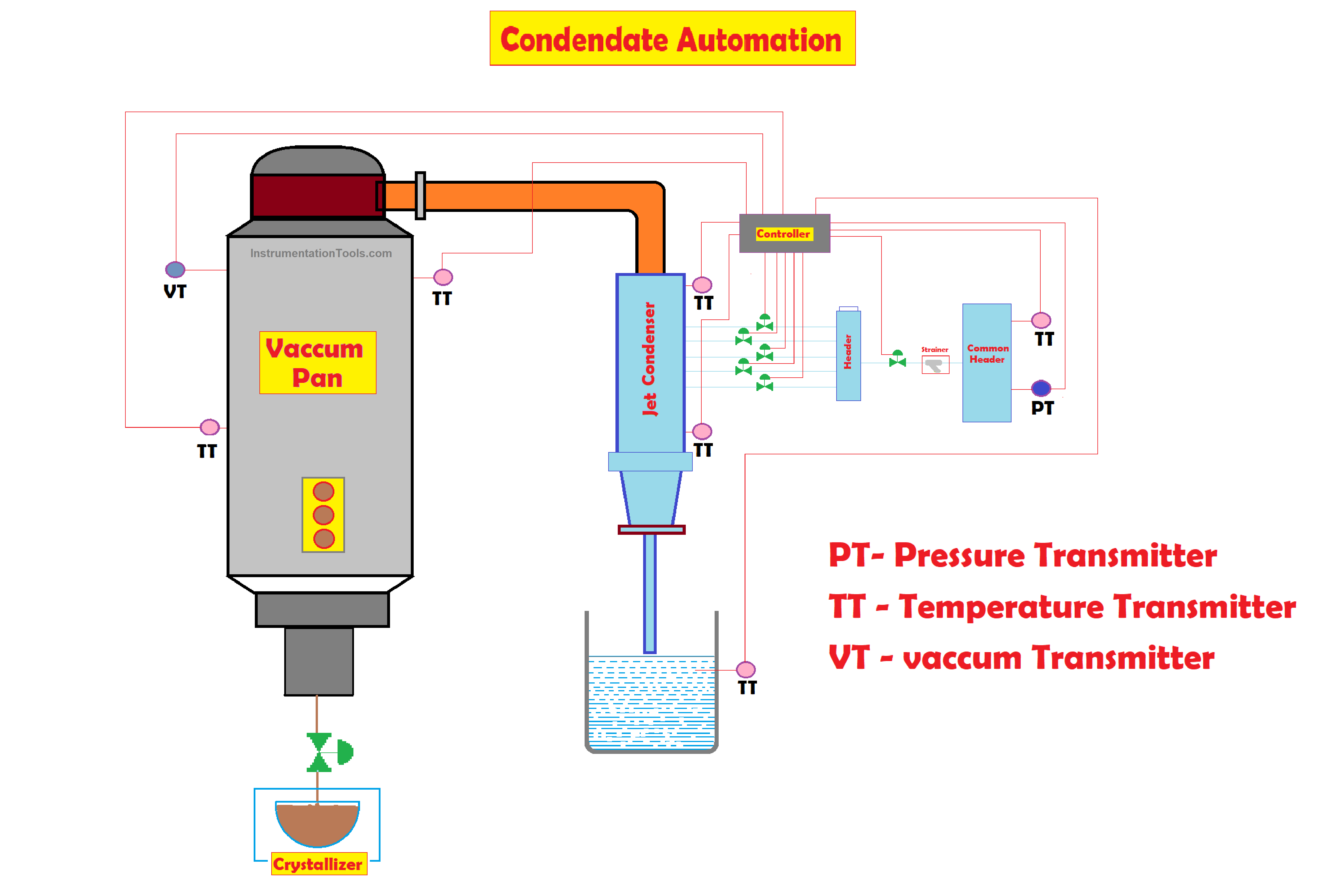
Jet Condenser Vessel and its Automation
- To reduce the temperature of vapor the vapors from the pan body enter the jet condenser.
- It is a multiple-entry condenser boxes.
- The condenser vessel is provided with multiple cold water entries with a set of spray nozzles and a spray jet.
- The on/off valve for the respective nozzle is used to control the spray water quantity in the jet condenser in auto mode.
- The strainer is provided to eliminate or remove the dust particles from the jet condenser vessel.
- The diameter of the spray jet & nozzle is designed as per condenser capacity.
- Here the spray water and jet nozzles are divided into 4 to 5 clusters.
- The inlet water is connected to stainless steel strainer.
- The temperature elements are installed to both the inlet and outlet of the jet condenser to sense the vapor temperature and send the signal to the controller through the temperature transmitter.
- The pressure of spray water in the common header is maintained by controlling the injection pump through a variable frequency drive.
- The inlet vapor temperature and tailpipe temperature were measured and controlled.
- The condensate automation system employs the temperature loop control system to control the temperature.
Working on Condensate Automation System in the Batch Pan
In the sugar manufacturing process, the massecuite boiling in the batch pan under vacuum conditions is very dynamic.
The process begins with the concentration of massecuite in the boiling phase at a batch pan.
To generate vacuum the condenser is used in manual mode since massecuite boiling is a batch type process and manual condenser is used.
There is no scope of water flow during the entire process. These results in excess use of water and the manual mode condenser are designed for peak vapor.
The NCG load and air load through leakage for an extreme condition do not alter the quantity of injection water with respect to vapor load and NCG load.
Whereas this NCG load is higher at the start of boiling and negligible at end of boiling.
This result in higher volume and high power consumption even after the vapor and NCG load are decreased due to massecuite thickening.
To achieve the temperature difference of 10 Degrees to 12 Degrees Celsius all ON/OFF butterfly valves are controlled with an interlock timer which is an important parameter of the technical performance of the condenser this is achieved without disturbing the vacuum in the pan body.
If the vacuum drops by 5mmHg after the closure of any valve. The Switch ON signal will be sent immediately to the respective valve to maintain the vacuum setpoint of 635mmHg.
Now the respective valves will be closed by the Switch OFF signal issued by the controller from the pan floor.
The valve remains in the ON position in case of air failure. The condenser continuously uses the recycled water from the spray pond cooling system.
Temperature Control Loop System
Basically, the temperature loop control system includes a Temperature control valve, Temperature sensor (TS), Temperature Transmitter (TT), PID Controller, I/P Converter,
Temperature Gauge
A temperature Gauge is the temperature sensing device that detects the hotness or coolness of the fluid flowing through the line and the body.
This temperature gauge is only for displaying the temperature.
Temperature Sensor
A temperature sensor is a temperature sensing device that detects the hotness or coolness of the fluid flowing through the line and the body.
This sensor sends the signal to the controller in terms of electrical quantity.
This system uses
- Vapour temperature sensor
- Inlet water temperature sensor
- Tailpipe temperature sensor
- Massecuite temperature sensor
Temperature Control valves
This unit reduces the temperature of the vacuum that consists of spray nozzles, through which cold water is sprayed to maintain the temperature difference of the vapor.
Positioner
A positioner in a control valve is a device that interfaces with the process controller that senses the exact position of the control valve.
The positioner sends the instrument air to the actuator so that the position of the valve stem changes according to the set point.
Controller
The controller receives electrical signals from all sensors installed at appropriate positions and sends appropriate signals to all the valves to maintain the temperature to desired set point.
Vacuum Transmitter
The vacuum transmitter (VT) senses the vacuum level and sends the signal to the controller for controlling the vacuum in the process.
- The stainless steel strainer is provided at the water inlet to prevent the entry of dust particles into the condenser.
- The temperature control valve regulates the quantity of the water to be sprayed.
- The water inlet and outlet isolation valves are used to isolate the temperature control valve whenever maintenance of the control valve is to be carried out.
- The bypass valve allows spray water flow to continue whenever the temperature control valve is under maintenance or becomes inoperable.
- The cold water is sprayed at high velocity through spray nozzles and at an adequate quantity to reduce the temperature of vapor to the required temperature.
- The temperature elements (TE) sense the temperature of the system installed in various locations and give a proportional current signal to the PID controller.
- The PID controller then compares the process variable (Measured Value) received from the temperature sensors with a given setpoint (SP), generates an error signal, and is then given to the positioner, which determines the position of the temperature control valve to maintain the temperature difference.
- This valve opens accordingly and sprays atomized water through the spray nozzle until the steam temperature reaches the set value, and re-closes to prevent the further spray of water after normal conditions have been restored,
i.e. Process Variable (PV) must be equal to SetPoint (SP). PV=SP