In the communication of data over networks, speed and latency matter the most. The higher the data speed transfer with lower error rates, the higher the chances for better and long-lasting communication. Many communication protocols are available in the networking system for data transfer. The most used one is Ethernet. But Ethernet can transfer data at a maximum of 100 meters.
To solve this, optical fiber communication is used. It is the most used method for transferring data at large distances and at the highest efficiency. Optical fiber communication is usually used for long distances; so, the cable also comes with open ends on both sides. To allow the ends to be used with communication ports, they must be joined with them.
For this reason, connectors must be used at both ends to align them with the ports. Readymade cables too come in the market of short lengths (typically 1 meter) for providing the required connectors. They are called patch cord cables. In this post, we will see the concept of fiber optics patch cord cable.
What is a Fiber Optic Patch Cord?
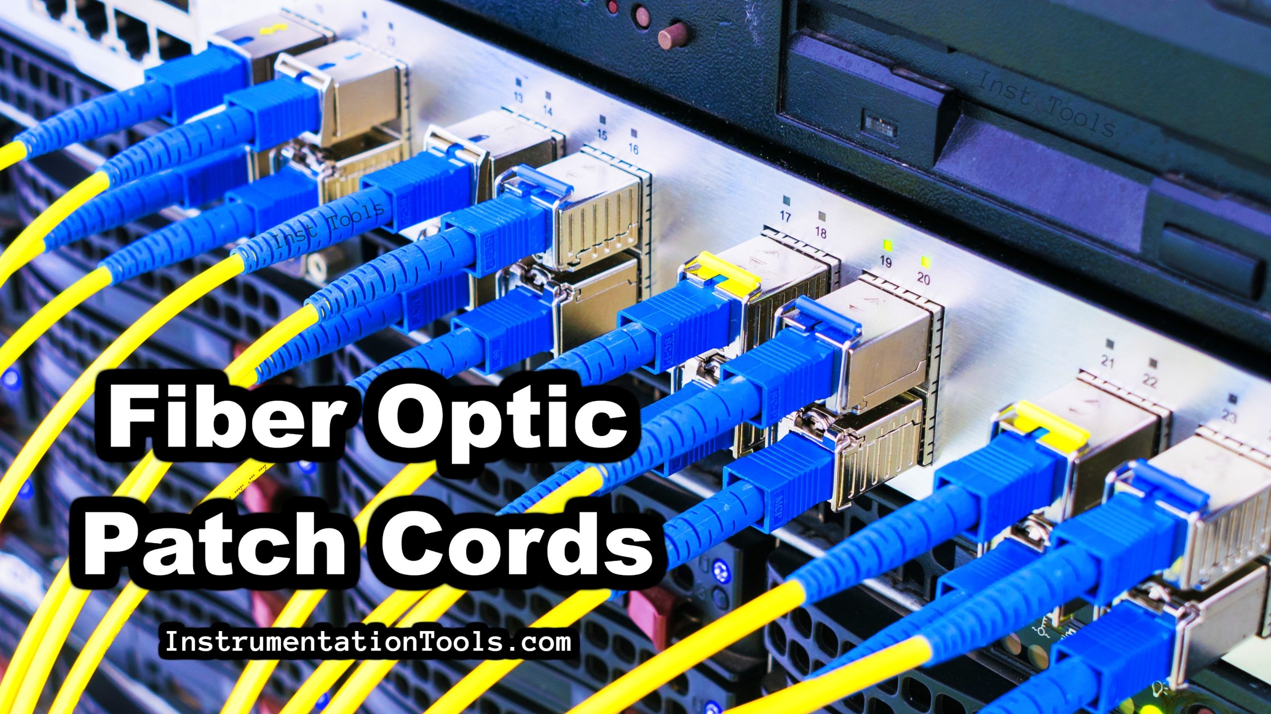
As discussed earlier, a fiber optic patch cord is a cable that is terminated at both ends by connectors like SC, ST, etc. to enable it to connect to the respective communication optical port. It means the cable is ready to use and just plug and play. They come in small length quantities, making it convenient to use quickly for applications like cable TV, home routers, optical laboratories in colleges, and other smaller types of network usage. There is no need to splice the cable (splicing means joining the open ends with connectors); just plug into the port wherever required and use it.
Fiber optic patch cords are composed of a fiber core and an outer PVC material package. The core inside is usually composed of glass material. A cladding is present above it (overlapped) and finally, a leather layer conduit is composed on it, which completes the structure. The above constitutes the fiber optic patch cord.
Types of Fiber Patch Cords
The fiber patch cords are classified as follows.
- Based on Mode
- Based on Fiber Strands
- Based on Connector Types
Based on Mode
There are two types – single mode and multi-mode.
In single mode, only one mode (path) of light is allowed to pass through the fiber core. It means only one data type can be transferred. The diameter is small and as only one path of light is passed; the data transfer speed is very high.
In multi-mode, multiple modes (path) of light are allowed to pass through the fiber core. It means that multiple types of data can be transferred. The diameter is large and as multiple paths of light are passed; the data transfer speed is a little slower than the single mode.
Based on Fiber Strands
As optical fiber is nothing but a strand of glass material inside, there are two types of strands – single and duplex.
In a single strand, only one strand of glass fiber is used with only one connector at both ends. In the duplex strand, two strands of glass fiber are used with two connectors each at both ends.
Based on Connector Types
As the connector is already pre-fitted with the cable, there are generally four types of connectors used – SC, ST, LC, and FC.
FC connectors are the oldest ones and use threaded metallic screw design. LC connectors use a plastic mold latch-type connection, which makes it simple to operate.
SC connectors are like LC ones but utilize a locking tab instead of a latch to secure the unit. This is the most used one as the body is made of plastic. ST connectors are like FC ones but instead of threads, they use a locking mechanism, and the body is made of metal like FC ones.
Comparison of Fiber Optic Patch Cords
The below table shows the comparison of different types of fiber optic patch cords based on various parameters such as core/cladding diameter, application, attenuation, and more.
| Parameter | Single-Mode Fiber Optic Patch Cord | Multi-Mode Fiber Optic Patch Cord | Polarization-Maintaining Fiber Optic Patch Cord | Armored Fiber Optic Patch Cord |
|---|---|---|---|---|
| Core/Cladding Diameter | 8.3/125 µm | 50/125 µm or 62.5/125 µm | 8.3/125 µm | Varies (both SMF and MMF) |
| Color | Yellow | Orange or Aqua | Blue or Yellow | Varies |
| Application | Long-distance data transmission | Short-distance data transmission | Specialized applications like instrumentation | Rugged environments |
| Attenuation | Lower (~0.4 dB/km at 1310 nm) | Higher (~3 dB/km at 850 nm) | Lower (~0.4 dB/km at 1310 nm) | Depends on the type of fiber |
| Bandwidth | Higher | Lower | Specialized, not usually a concern | Depends on the type of fiber |
| Connector Type | SC, LC, FC, etc. | SC, LC, FC, etc. | FC/APC, SC/APC, etc. | SC, LC, FC, etc. |
| Mechanical Strength | Normal | Normal | Normal | High |
| Cost | Higher | Lower | Highest | Higher than regular cords |
| Polarization Retention | No | No | Yes | No |
Detailed Explanations:
- Core/Cladding Diameter: Single-mode fibers have a smaller core diameter, allowing only one light mode to propagate. This minimizes modal dispersion. Multi-mode fibers have a larger core, allowing multiple modes, but this leads to higher modal dispersion.
- Color: The color codes help in identifying the type of fiber and are generally standardized.
- Application: Single-mode fibers are used for long-distance data transmission due to their lower attenuation and higher bandwidth. Multi-mode fibers are suited for short-distance applications like within a data center. Polarization-maintaining fibers are used in applications requiring the polarization state of light to be maintained. Armored fiber optic patch cords are used in environments where the cable needs to be protected from mechanical stress.
- Attenuation: Attenuation is generally lower in Single-Mode fibers compared to Multi-Mode fibers. This is due to fewer modal dispersion and scattering effects.
- Bandwidth: Single-mode fibers offer higher bandwidth capabilities due to lower modal dispersion.
- Connector Type: The connector types can vary, but some are more common for certain types of fibers. For example, APC (Angled Physical Contact) connectors are often used with polarization-maintaining fibers.
- Mechanical Strength: Armored fiber optic patch cords are specifically designed to withstand mechanical stress and are ideal for use in harsh environmental conditions.
- Cost: Single-mode fibers are generally more expensive due to the precision required in manufacturing them. Polarization-Maintaining fibers are the most expensive due to their specialized nature.
- Polarization Retention: Only Polarization-Maintaining fibers are designed to maintain the polarization state of the transmitted light.
I hope this table and the detailed explanations help you understand the differences between the types of fiber optic patch cords
In this way, we saw the concept of fiber optics patch cord cable.
If you liked this article, then please subscribe to our YouTube Channel for Electrical, Electronics, Instrumentation, PLC, and SCADA video tutorials.
You can also follow us on Facebook and Twitter to receive daily updates.
Read Next:
- Why Fiber Optic Cable is Spliced?
- Electrical Control Devices Questions
- Transducers Objective Questions
- Flow and Level Measurement Quiz
- Circuit Protection Devices Questions