Inst ToolsInst ToolsInst Tools
  • Courses
  • Automation
    • PLC
    • Control System
    • Safety System
    • Communication
    • Fire & Gas System
  • Instrumentation
    • Design
    • Pressure
    • Temperature
    • Flow
    • Level
    • Vibration
    • Analyzer
    • Control Valve
    • Switch
    • Calibration
    • Erection & Commissioning
  • Interview
    • Instrumentation
    • Electrical
    • Electronics
    • Practical
  • Q&A
    • Instrumentation
    • Control System
    • Electrical
    • Electronics
    • Analog Electronics
    • Digital Electronics
    • Power Electronics
    • Microprocessor
  • Request
Search
  • Books
  • Software
  • Projects
  • Process
  • Tools
  • Basics
  • Formula
  • Power Plant
  • Root Cause Analysis
  • Electrical Basics
  • Animation
  • Standards
  • 4-20 mA Course
  • Siemens PLC Course
Reading: T-Junction Traffic Control System – PLC Programming
Share
Font ResizerAa
Inst ToolsInst Tools
Font ResizerAa
  • Courses
  • Design
  • PLC
  • Interview
  • Control System
Search
  • Courses
  • Automation
    • PLC
    • Control System
    • Safety System
    • Communication
    • Fire & Gas System
  • Instrumentation
    • Design
    • Pressure
    • Temperature
    • Flow
    • Level
    • Vibration
    • Analyzer
    • Control Valve
    • Switch
    • Calibration
    • Erection & Commissioning
  • Interview
    • Instrumentation
    • Electrical
    • Electronics
    • Practical
  • Q&A
    • Instrumentation
    • Control System
    • Electrical
    • Electronics
    • Analog Electronics
    • Digital Electronics
    • Power Electronics
    • Microprocessor
  • Request
Follow US
All rights reserved. Reproduction in whole or in part without written permission is prohibited.
Inst Tools > Blog > PLC Tutorials > T-Junction Traffic Control System – PLC Programming

T-Junction Traffic Control System – PLC Programming

This article is about a T-junction traffic control system with the help of a PLC ladder logic using a comparator for lights operation.

Last updated: May 2, 2023 10:16 am
K Mugunthan
PLC Tutorials
No Comments
Share
7 Min Read
SHARE

This article is about a T-junction traffic control system with the help of a PLC ladder logic using a comparator for lights operation.

Contents
T-Junction Traffic Control SystemDescription of Inputs and OutputsPLC Programming and its ExplanationConclusion

T-Junction Traffic Control System

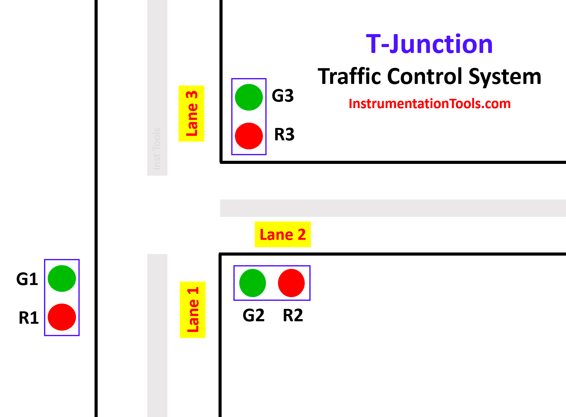
The function of the T-junction traffic control system consists of three groups of segments. By the logic of comparator operation, we control the Traffic lights system.
T-Junction Traffic Control System
  • First segment:

In the first segment, lane 1 traffic is allowed and lane 2 and lane 3 are stopped. Here in this segment, the green light (Green 1) of lane 1 glows, and red lights (Red 2) of lane 2 and (Red 3) of lane 3 glow. This period continues for fifteen seconds.

  • Second segment:

In the second segment, lane 2 traffic is allowed and lane 1 and lane 3 are stopped. Here in this segment, the green light (Green 2) of Lane 2 glows, and the red lights (Red 1) of Lane 1 and (Red 3) of Lane 3 glows. This period continues for fifteen seconds.

  • Third segment:

In the third segment, lane 3 traffic is allowed and lane 1 and lane 2 are stopped. Here in this segment, the green light (Green 3) of Lane 3 glows, and the red lights (Red 1) of Lane 1 and (Red 2) of Lane 2 glow. This period continues for fifteen seconds.

After the execution of all three segments, the sequence of operations again starts and repeats continuously.

Try PLC Courses – Advanced PLC Training

Description of Inputs and Outputs

In this PLC project, we used 2 Inputs, 6 Outputs, 2 Memory, and 1 On Delay Timer.

S.NoSymbolDescription
1I 0.0START
2I 0.1STOP
3M 0.0MEMORY
4M 0.1MEMORY 1
5Q 0.0GREEN 1
6Q 0.1RED 1
7Q 0.2GREEN 2
8Q 0.3RED 2
9Q 0.4GREEN 3
10Q 0.5RED 3
11DB1ON DELAY TIMER

PLC Programming and its Explanation

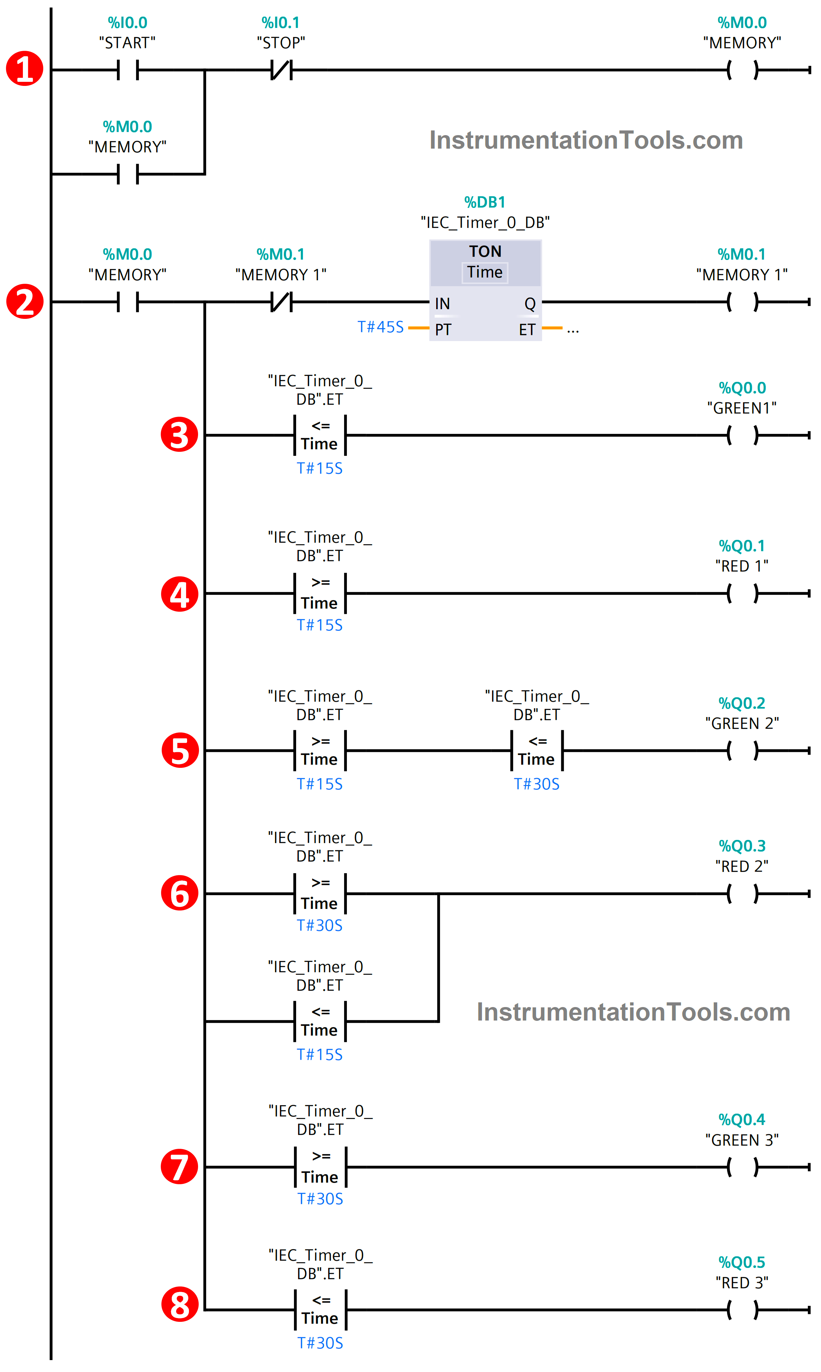
1. When the START (I 0.0) Button is pressed, MEMORY (M 0.0) is energized. This M 0.0 is the main memory used to execute all the processes in the program. Since it is latched, it will be in energized state only. If  STOP ( I 0.1) is pressed whole process will get stopped at any time.
T-Junction Traffic Control System PLC Program

2. Once MEMORY is energized, it will switch on the TIMER DB1 which controls the timing of the Traffic Junction. In this timer, we set the Pre-set time of 45 seconds. Once the timer achieves the pre-set time which energizes the MEMORY 1 (M 0.1) and this M 0.1 also resets the timer as per the logic and runs the cycle continuously.

3. Next, the comparator plays a major role in controlling the traffic junction. Firstly, the Output GREEN 1 (Q 0.0) is turned on as per the logic. Here we used Less than or Equal to the comparator. In this logic, Q0.0 will be in the ON state from 0 seconds to 15 seconds. After that, it will be going to OFF state

4. Next for output RED 1 (Q0.1), we used Greater than or Equal to function. Q0.1 will be in the ON state from 15 seconds to 45 seconds. It will be in the OFF state when Q0.0 is in the ON state.

5. Then for output GREEN 2 (Q0.2), we used both Less than or Equal to and Greater than or Equal to for this output. Both the comparator functions were connected in series logic connection with the output. In this Q0.2 will be in the ON state from 16 seconds to 30 seconds as per the condition.

6. Next for output RED 2 (Q0.3), we also used both Less than or Equal to and Greater than or Equal to function for performing the operation. Comparators were connected in parallel connection with the output. This output will be in the ON state from 0 seconds to 15 seconds and 30 seconds to 45 seconds. In between 15 seconds, it will be in the OFF state only since at that time Q0.2 is in the ON state.

7. Then for the last GREEN 3 output (Q0.4), we used Greater than or Equal to function. As per the conditional logic, it will be in an ON state from 30 seconds to 45 seconds. Before this timing, it will be in an OFF state.

8. Finally, the RED 3 output (Q0.5). Here we used Less than or Equal to function for executing the PLC logic. It will be in the ON state from 0 seconds to 30 seconds after that it will be in the OFF state.

Conclusion

So, in this way, the given T-Junction Traffic control is executed by the comparator function with the PLC logic. We can control the traffic logic with the help of PLC logic in many ways & this is also one of the ways in that.

If are you interested to learn another approach for traffic light control using PLC, then watch the below video.

PLC Traffic Light Example Program - Red, Yellow, Green Lights

If you liked this article, then please subscribe to our YouTube Channel for Instrumentation, Electrical, PLC, and SCADA video tutorials.

You can also follow us on Facebook and Twitter to receive daily updates.

Read Next:

  • PLC Restrict Data Interfaces
  • Use PLC Flags as Integrity Checks
  • Offline and Online UPS Systems
  • Diagnostic Buffer for SIEMENS PLC
  • Modbus Driver for SCADA System
Don't Miss Our Updates
Be the first to get exclusive content straight to your email.
We promise not to spam you. You can unsubscribe at any time.
Invalid email address
You've successfully subscribed !

Continue Reading

Difference between Cold Standby and Hot Standby
PLC Ladder Logic for Tanks Filling as per Priority
How to Install GSD File in Step 7 PLC using Simatic Manager?
Create a User-Defined Function Block in Codesys
Push button Motor PLC Logic
Timer during Motor Direction Change PLC Program
Share This Article
Facebook Whatsapp Whatsapp LinkedIn Copy Link
Share
Leave a Comment

Leave a Reply Cancel reply

Your email address will not be published. Required fields are marked *

Stay Connected

128.3kFollowersLike
69.1kFollowersFollow
210kSubscribersSubscribe
38kFollowersFollow

Categories

Explore More

Automate Batch Mixing with Repeated Cycles in Omron PLC
Interconnection between PLC, MCC, LCP & Pumps – Video
#9 PLC Best Practices – Validate indirections
Most Asked Questions on SCADA with Answers
Top 100+ SCADA Questions
Mixing Program with Timers and Counters in Omron PLC
Two Hand Press Safety Control Circuit
What is the OPC Server?

Keep Learning

Open User Communication in Siemens Tia Portal - PLC to PLC

Open User Communication in Siemens Tia Portal – PLC to PLC

How to Filter Digital and Analog Inputs in a PLC

#7 PLC Best Practices – Validate and Alert for Paired Inputs/Outputs

HMI Screen Design for Hazardous Applications

HMI Screen Design for Hazardous Applications

PLC Automatic Control of Two Outputs with one Input

PLC Automatic Control of Two Outputs with one Input

Classification of Fuses

Step-by-Step Guide to Choose Right Fuse for a Panel

Allen Bradley PLC ControlLogix Hardware

Allen Bradley PLC ControlLogix Hardware

Schneider Electric Modicon M340 PAC

PLC vs PAC – Understanding the Key Differences and Similarities

PLC Ladder Program for Automatic Car Wash

PLC Ladder Program for Automatic Car Wash using Siemens TIA Portal

Learn More

Adaptive Controller Overview

What is Adaptive Control?

Level Measurement Objective Questions

Level Measurement Objective Questions

Feedforward control with feedback trim

Feedforward Control Principle

Squirrel Cage Induction Motor Synchronous View

Squirrel Cage Induction Motor Animation

Difference between UPS and Stabilizer

Difference between UPS and Stabilizer?

Flanged Turbine Meter made flangeless for Bolting

Serious Constraints Prevent using an Available Turbine Flow Meter

Remote Factory Acceptance Test

Remote Factory Acceptance Test

Three Phase AC Generators

Three Phase AC Generators

Menu

  • About
  • Privacy Policy
  • Copyright

Quick Links

  • Learn PLC
  • Helping Hand
  • Part Time Job

YouTube Subscribe

Follow US
All rights reserved. Reproduction in whole or in part without written permission is prohibited.
Welcome Back!

Sign in to your account

Username or Email Address
Password

Lost your password?