Inst ToolsInst ToolsInst Tools
  • Courses
  • Videos
  • Q & A
    • Interview
      • Instrumentation
      • Electronics
      • Electrical
      • Practical Questions
    • MCQ
      • Instrumentation MCQ
      • Electrical MCQ
      • Electronics MCQ
      • Control Systems MCQ
      • Analog Electronics MCQ
      • Digital Electronics MCQ
      • Power Electronics MCQ
      • Microprocessor MCQ
      • Multiple Choice Questions
  • EE
    • Electronics
      • Electronics Q & A
      • Electronic Basics
      • Electronic Devices & Circuits
      • Electronics Animation
      • Digital Electronics
    • Electrical
      • Electrical Basics
      • Electrical Q & A
      • Power Electronics
      • Electrical Machines
      • Electrical Animation
      • Power Systems
      • Switchgear & Protection
      • Transmission & Distribution
  • Measure
    • Control Valves
    • Calibration
    • Temperature
    • Pressure
    • Flow
    • Level
    • Analyzers
    • Switches
    • Vibration
    • Solenoid Valve
  • Control
    • PLC Tutorials
    • Control Systems
    • Safety Instrumented System (SIS)
    • Communication
    • Fire & Gas System
  • More
    • Design
    • Tools
    • Animation
    • Basics
    • Formulas
    • Standards
    • TextBooks
    • Common
    • Software
    • Excel Tools
    • Erection & Commissioning
    • Process Fundamentals
    • Videos
    • Books
Search
All rights reserved. Reproduction in whole or in part without written permission is prohibited.
Reading: Effects of Long Distance Cables between VFD and Motor
Share
Notification Show More
Font ResizerAa
Inst ToolsInst Tools
Font ResizerAa
  • Courses
  • PLC Tutorials
  • Control Systems
Search
  • Courses
  • Videos
  • Q & A
    • Interview
    • MCQ
  • EE
    • Electronics
    • Electrical
  • Measure
    • Control Valves
    • Calibration
    • Temperature
    • Pressure
    • Flow
    • Level
    • Analyzers
    • Switches
    • Vibration
    • Solenoid Valve
  • Control
    • PLC Tutorials
    • Control Systems
    • Safety Instrumented System (SIS)
    • Communication
    • Fire & Gas System
  • More
    • Design
    • Tools
    • Animation
    • Basics
    • Formulas
    • Standards
    • TextBooks
    • Common
    • Software
    • Excel Tools
    • Erection & Commissioning
    • Process Fundamentals
    • Videos
    • Books
Follow US
All rights reserved. Reproduction in whole or in part without written permission is prohibited.
Inst Tools > Blog > Electrical Basics > Effects of Long Distance Cables between VFD and Motor

Effects of Long Distance Cables between VFD and Motor

In this post, we will learn the effect of the long distance cables between VFD and motor, and why it must be avoided.

Last updated: December 7, 2022 12:13 pm
Viral Nagda
Electrical Basics
2 Comments
Share
6 Min Read
SHARE

The Variable Frequency Drive (VFD) is a very important element in motor speed control. You can get any desired speed with the use of VFD.

But, do you know that the distance between a motor and a VFD matters too? It may not sound too interesting, but it is a fact that the distance between the motor and the VFD is one of the important factors in running a motor efficiently and for longer life.

In this post, we will learn the effect of the long distance between VFD and motor, and why it must be avoided.

Why must the distance between the Motor and VFD be Shorter?

Effects of Long Distance Cables on VFD

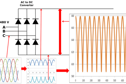
It must be noted that the typical distance between VFD and the motor should not exceed 30 meters. Why? Let us get into the fundamentals now. The output of VFD is a sine wave. For a variable sine wave to properly control the speed of the motor, the cables, VFD, and motor must all be properly grounded. This is the very first step in the topic.

Now, as we are discussing the cable length, the cable must be properly shielded in its very first place. If the cable is properly armoured and grounded, then the noise generated within the cable is confined to itself only.

Otherwise, the noise will be disbursed outside the cable too, and the higher the noise, the higher will be the leakage current generated. And if the distance is long, then the noise will spread over more area, and the chances of the motor getting damaged will increase more. So, this is the very first step in distance point – the cables must be properly grounded, be they shorter or longer distances.

Now, let us move on to the next point. It is to be noted that a capacitance always exists in the sine wave current (PWM signal) flowing in VFD cables to the motor. One of the main issues faced in this is voltage reflection. When the distance is long, the impedance of the power cables and the motor is not consistent. It is mostly consistent in shorter distances.

Now, if a normal PWM signal is flowing and if this impedance collides with it, then there will be high chances of voltage reflection. Impedance plays a very important role in PWM signals. When the drive sends output sine waves down the cable to the motor, they reach the motor and due to the motor’s impedance, reflect back towards the drive, while the drive is continually sending sine waves to the motor.

Coming back to the earlier point of the effect of capacitance, the capacitance from the cables (phase to ground) too can create enough current to ground where there can be nuisance ground fault trips.

These two factors – capacitance and voltage reflections due to improper impedance, can cause the reflected wave could be added to the fundamental waveform coming from the drive resulting in a significantly higher voltage at the motor terminals.

So, if the distance is longer, then there will be more chances of unbalanced voltage peaks in between (due to the issue discussed earlier). This will also increase rise steepness (dv/dt) to a large extent. If the rise is more and unstable, then the voltage peaks will occur frequently.

Both the maximum value of the voltage pulse and the rise steepness (dv/dt) are dangerous for the motor insulation. Due to this, the motor will not operate properly, and also, after a certain period of time, the insulation and bearings of the motor will get damaged.

The long-distance connection will generate surge voltage at both ends of the motor winding, the superimposed surge voltage will increase the winding current of the motor and the motor temperature, thus damaging the winding insulation.

This shows that the distance between VFD and the motor must be tried to keep not too long. There are many ways to counter this; because suppose you are placing a VFD in the central room, then the motor will always be at a larger distance at the field site. It is a completely different topic, and we cannot elaborate here. Our main purpose was to first understand the effect of the long distance between the VFD and the motor.

In this way, we understand the effects of long-distance cables on VFD and motor.

If you liked this article, then please subscribe to our YouTube Channel for Electrical, Electronics, Instrumentation, PLC, and SCADA video tutorials.

You can also follow us on Facebook and Twitter to receive daily updates.

Read Next:

  • Auto Changeover Switch
  • How do AC Drives Work?
  • What is a Solid State Relay?
  • What is Transformer Bushing?
  • Variable Frequency Drive (VFD)
Don't Miss Our Updates
Be the first to get exclusive content straight to your email.
We promise not to spam you. You can unsubscribe at any time.
Invalid email address
You've successfully subscribed !

Continue Reading

Automatic Transfer Switch (ATS) Using Classic Control Circuit
Worldwide Voltage & Frequency Values
Types of Electrical Loads
What is a Link Box?
Difference Between Metering CT and Protection CT
Why V/f Ratio is kept Constant in VFD?
Share This Article
Facebook Whatsapp Whatsapp LinkedIn Copy Link
Share
2 Comments
  • Darren Ash says:
    December 14, 2022 at 5:17 am

    Have never heard the output of a VFD described as a sine wave. You would need a sine wave filter for that function to convert from PWM output to an actual sine wave.

    You get to the description later in the article, but takes effort to get from PWM to an actual sine wave. dv/dt will help with peaks but on a scope still looks like a PWM signal.

    All VFD manufacturers I have worked with have technical documents that cover required cable specifications based on distances and the needed reactors or filters depending on distance. You must refer to the manufacturer recommendations as not all drives have equivalent control algorithms. Some have software based reflective wave mitigation built-in to the firmware that may require different recommendations than another vendors drive.

    Reply
  • AMIN MOHAMMADI says:
    August 14, 2023 at 3:33 pm

    Dear engineer , Viral Nagda
    Hello
    Thank you for your very helpful and clearly written article. And I wish you the best.
    I thank all the staff of the site ” Instrumentationtools.com”

    Reply

Leave a Reply Cancel reply

Your email address will not be published. Required fields are marked *

Stay Connected

128.3kFollowersLike
69.1kFollowersFollow
208kSubscribersSubscribe
38kFollowersFollow

Categories

Explore More

Things to Know When Measuring Current
VFD Simulator Download – Free Yaskawa V1000 Software
UPS Working Principle and Types – Offline and Online UPS Systems
MCB vs Fuse Questions and Answers
How Motor Star Delta Starter Works ?
Difference between RCCB and RCBO
What is Floating Neutral? – Electrical Engineering Basics
One Nation One Grid One Frequency – Electrical Engineering
Difference between Stepper Motor and Servo Motor
Geothermal Energy Power Plants

Keep Learning

Applications of Electrical Conduit System

What is an Electrical Conduit? – Types – How to Choose?

Three phase induction motor nameplate

How to Size a Cable for Industrial AC Motors?

Electrical Equipment Selection in Hazardous Area

Hazardous Areas in Industry – Electrical Equipment Selection

Difference between PVC, XLPE, and Insulated Cables

Difference between PVC, XLPE, and Insulated Cables

Lead Acid Battery Operation

How does a Lead Acid Battery Work?

Difference between Power Cables and Signal Cables

Difference between Power Cables and Signal Cables

Motor Controls

Design and Implement Motor Control – Electrical Engineering

Difference Between Wattmeter and Energy Meter

Difference Between Wattmeter and Energy Meter

Discover More

process conditions, Find out the Circuit Components Status

As per Process Conditions, Find out the Circuit Components Status ?

Stability in Frequency Domain

Cascade Compensation in Time Domain

Effects of Capillary Tubing on Pressure Measurement

Capillary Tubing Pressure Sensor Temperature & Elevation Problems

Fieldbus Flow Transmitter Calibration

Foundation Fieldbus Transmitter Calibration

U-tube Manometer unEqual Limb Type

U-tube Manometer with equal & unequal limb types

CNC Machining vs 3D Printer

CNC Machining vs 3D Printer – What is the difference?

Moisture Separator

Inhouse Moisture separator for Pneumatic Systems

What is PLC

What is a PLC? – Programmable Logic Controller

Follow US
All rights reserved. Reproduction in whole or in part without written permission is prohibited.
Welcome Back!

Sign in to your account

Username or Email Address
Password

Lost your password?