Inst ToolsInst ToolsInst Tools
  • Courses
  • Automation
    • PLC
    • Control System
    • Safety System
    • Communication
    • Fire & Gas System
  • Instrumentation
    • Design
    • Pressure
    • Temperature
    • Flow
    • Level
    • Vibration
    • Analyzer
    • Control Valve
    • Switch
    • Calibration
    • Erection & Commissioning
  • Interview
    • Instrumentation
    • Electrical
    • Electronics
    • Practical
  • Q&A
    • Instrumentation
    • Control System
    • Electrical
    • Electronics
    • Analog Electronics
    • Digital Electronics
    • Power Electronics
    • Microprocessor
  • Request
Search
  • Books
  • Software
  • Projects
  • Process
  • Tools
  • Basics
  • Formula
  • Power Plant
  • Root Cause Analysis
  • Electrical Basics
  • Animation
  • Standards
  • 4-20 mA Course
  • Siemens PLC Course
Reading: Partial Discharge in Power Lines and its Detection through Sensors
Share
Font ResizerAa
Inst ToolsInst Tools
Font ResizerAa
  • Courses
  • Design
  • PLC
  • Interview
  • Control System
Search
  • Courses
  • Automation
    • PLC
    • Control System
    • Safety System
    • Communication
    • Fire & Gas System
  • Instrumentation
    • Design
    • Pressure
    • Temperature
    • Flow
    • Level
    • Vibration
    • Analyzer
    • Control Valve
    • Switch
    • Calibration
    • Erection & Commissioning
  • Interview
    • Instrumentation
    • Electrical
    • Electronics
    • Practical
  • Q&A
    • Instrumentation
    • Control System
    • Electrical
    • Electronics
    • Analog Electronics
    • Digital Electronics
    • Power Electronics
    • Microprocessor
  • Request
Follow US
All rights reserved. Reproduction in whole or in part without written permission is prohibited.
Inst Tools > Blog > Electrical Basics > Partial Discharge in Power Lines and its Detection through Sensors

Partial Discharge in Power Lines and its Detection through Sensors

In this post, we will understand the theory of partial discharge in power lines and how it is detected through sensors.

Last updated: September 28, 2022 4:09 pm
Viral Nagda
Electrical Basics
No Comments
Share
6 Min Read
SHARE

In this post, we will understand the theory of partial discharge in power lines and how it is detected through sensors.

Contents
Partial Discharge in Power LinesDetection Methods of Partial DischargeOnline MethodOffline MethodDetection System

In electrical systems, insulation between conductors is a big factor in deciding its performance. Bad insulation can partially or completely break down the system.

Partial Discharge in Power Lines

Often, a common issue roots up in insulation and it damages the system; named partial discharge. Partial discharge is a consequence of local electrical stress (normally caused in high voltage lines) on the insulation system.

Partial Discharge in Power Lines and its Detection through Sensors

Due to this, a discharge occurs in insulators, as the insulation between conductors is partially bridged now. Insulation is a protection layer for the conductor; and if this insulation fails, then it will indirectly damage the electrical system.

During discharge, various types of exchange of energy take place; which can be classified as – dielectric losses, light (M radiation), noise, gas pressure, chemical reactions, and electrical pulse currents. It depends on the type of media used in insulation (solid, liquid, or gas).

Simply, for example, consider there is a void or impurity in insulation, caused by stress. When a high voltage is applied to the conductor, an electric field is also induced in this void.

Further high voltage can break down the insulation and it will then discharge different forms of energy; which can be termed partial discharge.

Partial discharge normally starts within gas voids of the insulation, which are created by voltage stress or have occurred during the manufacturing stage when a poor vacuum was provided.

The dielectric constant of this void is lower than the dielectric of the surrounding. Lower dielectric means higher chances of getting voltage stress. When this void is then subjected to constant high voltage stress, discharge starts happening continuously from it.

As the power cables are longer in length, there will be several such voids present in them and it will overall break down the system after a period of time.

Because the gap of the void goes on increasing if there is no control, there will be the stage where insulation will be of no use and the system will fail.

Detection Methods of Partial Discharge

So, every power distributor needs a mechanism to detect partial discharge; to avoid failure of the system in long run.

Normally, there are two methods of detecting partial discharge – online and offline.

Online Method

In the online method, detection is done in real-time conditions; that means at a regular operating voltage of the cable, operating temperature, and voltage stress.

It reduces time, prevents special shutdown required, and is less costly.

Offline Method

In the offline method, as the name implies, detection is done in offline conditions; that means the system is shut down specially or sometimes, removed from the distribution system.

Though it takes time, it provides greater accuracy; as you get all the time to test and also apply higher voltages. This method is costlier than the online process.

Detection System

If you see its detection system, generally consists of a PC software for troubleshooting, a high voltage filter to reduce background noise from the power supply, a partial discharge detector, high-voltage connections, and a coupling capacitor of low inductance design.

Let us understand how its detection system works. It is to be noted that partial discharge currents are short in duration and have high rise time peaks.

So, if you observe it in an oscilloscope waveform, it will clearly appear as bursts at the peak of the sine wave. This peak is graphed against time.

Then, a method called time domain reflectometry (TDR) is used to detect the location of the discharges. They are then displayed on the software in its format and so, used for troubleshooting further.

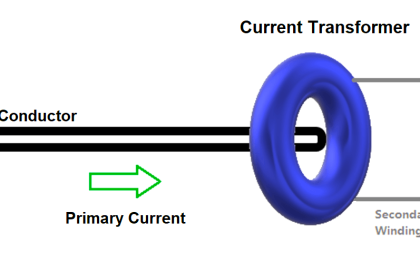
The types of detectors used in analyzing are – UHF (Ultra High Frequency) sensors for detecting electromagnetic waves, HFCT (High-Frequency Current Transformer) for detecting high peak currents by inducing its emf in the secondary windings and then sending this information to PC and TEV (Transient Earth Voltage) sensor to detect TEV signal or earth noise signal representing PD inside.

There are some sensors too that combine the above three methods to provide more accurate and efficient output.

Partial discharge is a grave problem if not detected at an early stage and so, it is important to either analyze it in the production stage itself; or monitor it on a regular basis when in use.

In this way, we saw the concept of partial discharge in power lines.  

Don't Miss Our Updates
Be the first to get exclusive content straight to your email.
We promise not to spam you. You can unsubscribe at any time.
Invalid email address
You've successfully subscribed !

Continue Reading

How Do Air Compressor Filters Clean and Protect the System?
What is ELCB? Principle, Advantages, Disadvantages, Applications
What are Static UPS and Rotary UPS?
What is a Time Delay Fuse? – Principles and Advantages
4-20mA Linear Conversion Calculation for VFD Drive (Formula)
Why Are Charcoal and Salt Added to an Earthing Pit?
Share This Article
Facebook Whatsapp Whatsapp LinkedIn Copy Link
Share
Leave a Comment

Leave a Reply Cancel reply

Your email address will not be published. Required fields are marked *

Stay Connected

128.3kFollowersLike
69.1kFollowersFollow
210kSubscribersSubscribe
38kFollowersFollow

Categories

Explore More

Lithium-ion Battery Charging Systems
Why do we need to Control the Motion using VFD drives?
Circuit Breaker Testing – Routine Tests of Circuit Breakers
What is a Power Transformer? – Components and Types
Contactor – Basics, Wiring, Connection with PLC
Bus Riser in Switchgear
What is Torque Boosting in Variable Frequency Drive (VFD)?
100 Electronics and Electrical Projects for Engineering Students

Keep Learning

How to Locate Faults in Cables? - Fault Analysis and Location

How to Locate Faults in Cables? – Fault Analysis & Location

Understanding Protection Relays

Understanding Protection Relays – 50, 50N, 51, 51N

Difference between PVC, XLPE, and Insulated Cables

Difference between PVC, XLPE, and Insulated Cables

Electrical Link Box

What is a Link Box?

Difference between Stepper Motor and Servo Motor

Types of Inductors

What is an Inductor? – Types of Inductors

Flame Cables

Difference Between Flame Resistant and Flame Retardant Cables

MCCB (Molded Case Circuit Breaker)

Industrial Circuit Breakers – Most Common Types – Principle

Learn More

Cable Gland Parts

What is a Cable Gland ?

Power Electronics Objective Questions

Single-Phase Full Wave AC-DC Converter Test

Guided Wave Radar Questions and Answers

Guided Wave Radar Questions and Answers

How to identify location of Fire Detectors

How to identify location of Fire Detectors

Under and Over-Capacity Control Valve

Under and Over-Capacity Control Valve Pose Poor Controllability

Vibration Sensors Theory

How Vibration sensors Work ?

Cutaway View of Circuit Breaker

Low Voltage Air Circuit Breaker Principle

Configuration of Siemens Scada and PLC

#12 PLC Best Practices – Validate Inputs based on Physical Plausibility

Menu

  • About
  • Privacy Policy
  • Copyright

Quick Links

  • Learn PLC
  • Helping Hand
  • Part Time Job

YouTube Subscribe

Follow US
All rights reserved. Reproduction in whole or in part without written permission is prohibited.
Welcome Back!

Sign in to your account

Username or Email Address
Password

Lost your password?